
A New Face To Parts Chucking
Mechanical face drivers offer an alternative to other types of traditional chucking methods. Using mechanical face drivers for turning applications often provides increased flexibility and lower cycle times. Face drivers turn both very small and very large workpieces, and they also allow interrupted and heavy cuts. The major benefit of a face driver is that it allows the workpiece to be completely turned from one end to the other in one operation.


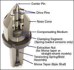
This cutaway view of a mechanical face driver identifies the key components of its construction.
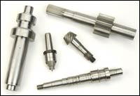
These parts typify the range that is produced with today’s face drivers. The longest piece is more than 15 inches and weighs 22 pounds, but parts much longer and much shorter are also common.
Mechanical face drivers deserve a closer look as an alternative to other types of traditional chucking methods. In many cases, using mechanical face drivers for turning applications provides increased flexibility and lower cycle times. The major benefit of a face driver is that it allows the workpiece to be completely turned from one end to the other in one operation.
Few Limitations
It was once thought that face drivers were primarily for long and straight cylindrical shafts that had to be turned between centers. Now many manufacturers find that anything that can be turned between centers can be done with a face driver.


Some workpieces that are routinely cut using face drivers include automotive transmission parts, crankshafts, camshafts, pinion gears, electric motor shafts, forgings and axles up to 36 inches in diameter. To be safely turned with a face driver, a three-to-one ratio of drive diameter to rough workpiece diameter is recommended, but five-to-one ratios have also been used.
At one time, heavy cuts were thought to be a problem issue with face drivers because of part slippage. This is no longer true, especially with mechanical face drivers. With proper center pin loading and the use of drive pins (some applications do not require drive pins; for example, certain face drivers used in gear hobbing applications include a drive disk system to avoid slippage), almost any type of part can be turned and often with greater efficiency than when using a jawed chuck.
Interrupted cuts were also generally thought to be unacceptable for face drivers, but today, these types of cuts can be done with fast feeds and deep cuts. Plunge cuts, or grooving interrupted cuts into hardened gears, as well as hard threading are routinely done today with face drivers.
Face drivers can handle a wide range of workpieces with one size driver. For example, by changing the drive pins, Neidlein’s size 4 models (both spring-loaded and fixed-center versions) can handle workpieces from 1.575 to 7.0 inches in diameter.
Other applications, such as hard turning, grinding, gear hobbing and milling, also lend themselves to face driving. For example, gear hob clearance can be an issue for many types of workholding, but with the correctly specified and implemented face driver, this application can be very successful. Spring-loaded center pins using a drive disk (instead of drive pins) work well for hobbing. The drive disk can be quickly changed for sharpening or replacement because it is easy to remove.
The Rules
Two rules apply to using face drivers.
First, the application must have a machine that can deliver sufficient tailstock force to hold the workpiece. However, force depends on the type of workpiece being turned, the material it is made from, the number of drive pins used in the face driver and what type of operation is being performed (turning, grinding, hard turning, gear hobbing and so on). If there is doubt as to how much force is needed, users are advised to consult the face driver manufacturer for guidance. Generally, most machines have enough tailstock force for a mechanical face driver, although manual tailstock grinders and engine lathes are exceptions.
Second, the first cut should generally be towards the face driver to better set the workpiece and allow the drive pins to do their work by biting into it. Once the first cut is made towards the face driver, then cuts toward the tailstock can be made. Grinding and hard turning applications may not need to follow this rule, however.
Face Driver Design Components
Face drivers have four main parts:
Flange/shank: A flange mount or shank mount is used to attach the face driver to the turning center.
Nose cone: This area of the face driver (attached to flange/shank area) is the housing and guide for the drive pins, center pin and its compensating mechanism/spring-loading system. The compensating mechanism/spring-loading system allows the drive pins to adjust for any variation in flatness of the workpiece’s end. In some mechanical designs, a convex/concave washer system works with the spring-loaded or fixed-center pin to allow the system to accommodate irregularly faced workpieces (typically found in unevenly sawed parts or near-net-shape cast or forged parts).
Center pin: At the center of the face driver is a center pin that holds the workpiece on center line to the other center (or tailpiece support) on the opposite side, which is generally a tailstock/footstock with a live or dead center. A live/dead center is used to center the workpiece and locate its point in the workpiece’s center hole. Center pins can be changed for different types and sizes of workpieces. (For example, hardened workpieces typically require a carbide center pin or different diameters of center sizes.) They center the workpiece to rotate along the machine’s axis and permit the drive pins to engage the workpiece’s face. Widely accepted in industry today is the spring-loaded center pin design, which includes length positioning from the drive pin or face of the workpiece. Fixed-center pins (length measurements are taken from a gauge ball versus the face of the workpiece) are also available. Fixed center versions provide the most precise runouts, with TIR measurements as low as 0.0002 inch compared to the 0.0004-inch TIR that is typical on spring-loaded designs).
In fixed-center face drivers, a hydraulic or pneumatic actuator pushes the drive pins into the workpiece, whereas with spring-loaded types, the tailstock pushes the workpiece to the drive pins. In cases using a fixed center driver (when extremely high tolerances are needed or where lengths are measured from the center hole using a gauge ball), you must have the right size actuator and drawbar to avoid overpowering the tailstock and to optimize the machine’s hydraulic/pneumatic system.
Drive pins: To turn a workpiece efficiently, drive pins should act as teeth that bite into the workpiece’s face. These pins are replaceable and are available in sets of three, five or six, depending on the size of the driver and the workpiece being turned.
Some applications require drive pins that are coated with materials such as carbide or diamond. Metal workpieces with a hardness of Rockwell C 48 or higher should use coated drive pins. Diamond coated pins are still used for grinding hardened workpieces. Grinding does not generate as much force as turning.
Drive pins that are micro-serrated and hard-coated are available. These pins reduce or eliminate part slippage, thus reducing scrap. They also last longer than diamond-coated drive pins.
Finishing hardened workpieces using face drivers is gaining greater acceptance with the advanced capabilities of face drivers, machine tools and cutting tools. However, a drawback has been the ability to clamp hardened workpieces reliably and accurately while machining them entirely in a single operation. To ensure proper workholding, a suitable driving element—one which can handle high-tolerance demands and still be cost effective to make hard turning possible—is needed. One option is a system of micro-serrated and hard-coated drive pins mounted around the face driver (which has been successful in many turning applications, but especially hard turning).
Life expectancy for micro-serrated and hard-coated drive pins is reported to be six to ten times longer than that of diamond-coated pins in hard turning and grinding applications. The new pins are more reliable than diamond-coated pins, which can lose grip if the diamond coating chips off under tough conditions such as turning hardened workpieces. In addition, these pins can grip a smaller surface area, allowing them to handle a greater variety of workpieces than diamond-coated pins can.
Given the proper parameters, these drive pins are said to achieve roundness tolerances of less than 0.000008 inch (0.002 mm) in long production runs.
Mechanical Or Hydraulic?
While both types are widely used, mechanical face drivers seem to provide stronger reasons for selection than hydraulic face drivers. Mechanical models have compensating drive pins and minimal center runout resulting from the extended guide length on center, the center pin and its locking mechanism (in spring-loaded models only). The center point is mechanically locked when it is in the clamped position. These face drivers offer accuracy below 0.0004-inch TIR. Part diameters that can be driven range from 0.240 inch to 36 inches in diameter on standard face drivers. (Smaller and larger diameters have been machined with special application face drivers).
Mechanical styles can be used with workpieces weighing as much as 8,000 lbs (whereas typical hydraulic face drivers are said to be limited to workpieces half as heavy). Turning longer workpieces may require the use of a steady rest for additional support.
The typical mechanical face driver requires less tailstock force because 90 to 95 percent of this force is available for the drive pins to bite into the workpiece, with 5 to 10 percent of the tailstock force used to collapse the center pin. In hydraulic face drivers, about 50 percent of the tailstock force is used to collapse the center pin because they have no center pin locking mechanism.
Cost Savings And Other Notes
Other benefits of face drivers are reduced energy costs, as well as less wear and tear on the spindle and on the machine’s internal components. It takes more energy to spin a large chuck mounted on the machine than it might with a small face driver. Mechanical face drivers may also reduce maintenance costs. Applying grease when changing drive pins is usually all that is required.
On live/dead centers, the face driver is typically only as good as the tailstock center. Carbide-tipped centers work well in hard turning and grinding applications. Choose a tailstock center designed to minimize runout error, withstand high axial and radial loads, and require little maintenance.
About the author. Brandon Morris is the Neidlein product manager at LMC Workholding, Logansport, Indiana.


Related Content

IMTS Takeaways From the Modern Machine Shop Editorial Team
The first in-person IMTS in four years left the MMS editorial staff with a lot to digest. Here are a few of our takeaways from the show floor.
Read More
Modern Bar Feeds Bring New Life to Automatic Swiss Lathes
Cam-actuated Swiss lathes are still the fastest way to process many parts. By adding modern bar feeders, this shop has dramatically improved their utilization with the ability to work unattended, even in a lights-out environment.
Read More
When To Use A Collet Chuck
Don't assume the standard chuck is the right workholding for every lathe application.
Read More
Simple Workholding for Robotic Automation
Robotic automation relies on reliable workholding, and these modular pneumatic jaws make it simple.
Read MoreRead Next

When To Use A Collet Chuck
Don't assume the standard chuck is the right workholding for every lathe application.
Read More
The Cut Scene: The Finer Details of Large-Format Machining
Small details and features can have an outsized impact on large parts, such as Barbco’s collapsible utility drill head.
Read More
