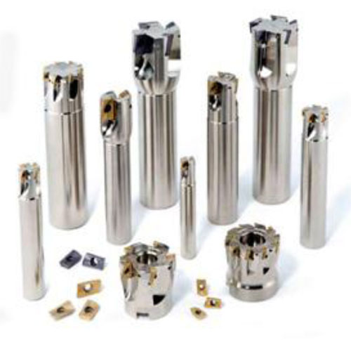
In the first article, we discussed milling history, milling operations, and cutter types. Here we will explain design and application considerations related to various milling choices.
Most of these design considerations involve cutting tool geometry:
- Lead angle is the approach angle of the cutting edge as it enters the workpiece. The lead angle controls the direction of the radial cutting force and axial cutting force.
- Rake angle is the incline of the top surface of the cutting edge that makes contact with the chip. The rake controls the degree of cutting forces and cutting edge strength.
- Clearance angle is the angled relief behind the cutting edge that eliminates interference between the cutting tool and the workpiece.
- Cutter diameter is the maximum flat surface a cutter will machine.
- Insert pitch is the distance between corresponding positions on one insert to the same position on the subsequent insert.
- Insert density is the number of inserts, or cutting edges, per inch of diameter.
- Hand of cut determines the cutter rotation direction. Milling cutters are designed to cut clockwise or counterclockwise.
- Mounting adaptation is determine by the type of machine spindle on which the rotating cutter is mounted. The method of mounting is a major factor in determining the rigidity and performance capability of the cutter.
The lead angle of a face-milling cutter is the approach angle of the cutting edge in relationship to the workpiece and is measured off the axis of the cutter. The lead angle's relationship to the cutter and spindle axis impact tool performance and productivity significantly, which in turn affects workpiece quality. In this article series, we refer to the ISO norm for lead angle (example: square shoulder = 90 degrees).
The lead angle provides five primary design functions:
- It controls the balance between radial and axial feed forces. As the lead angle decreases, radial forces decrease and axial forces increase.
- It affects workpiece chipping and burring on the exit side of cutter rotation. When feed forces exceed the strength of material, chipping or burring occurs.
- It affects face engagement between the insert and workpiece. Low lead angles leave very little face clearance, which creates a large face engagement. A high lead angle will have a smaller overall contact area when comparing similar depths of cut.
- It provides effective chip thinning. As the lead angle decreases, chip thickness also decreases, often requiring higher overall feed rates.
- A lead angle protects the nose of the insert by moving the first point of contact away from the most fragile portion of the insert.
Certain applications are restricted to specific lead angles. For example, the lead angle distinguishes general face milling from square-shoulder milling. With square-shoulder milling, the lead angle is 90 degrees, designed to produce a square shoulder in the workpiece and allow machining close to walls and fixture clamps.
There are numerous lead angles available for standard face milling cutters. Low lead angles leave very little face clearance, which creates a large face engagement. A large face engagement can work-harden the workpiece surface, which reduces tool life if feedrate is not increased to compensate for the chip-thinning effect.
Hexagonal and octagonal inserts also produce a large face engagement. Cutters with lower lead angles should be used only when square shoulders are required. Higher lead angles leave more face clearance. For machining-center milling applications in which metal-removal rate and surface finish are important, a 45-dgree lead angle is recommended. Note, however, that power consumption changes very little with changes in lead angle.
The Rake Angle
The rake angle is the inclination of the top surface of the cutting edge, or the surface that makes contact with the chip. The rake angle is measured in two planes, providing axial rake and radial rake. With milling tools, the rake is usually designed independent of the lead angle. Rakes can be positive, neutral, or negative in both the axial and radial planes.
The cutting edge is always positioned on centerline, and the rake moves the face of the insert ahead of or behind centerline to create one of the following:
- Neutral radial rake indicates that the face of the insert lies on the radial centerline of the cutter.
- Positive radial rake indicates that the cutting edge is positioned on the radial centerline of the cutter. The top surface of the cutting edge slopes back and away from the radial centerline.
- Negative radial rake indicates that the cutting edge is positioned on the radial centerline of the cutter. The top surface of the cutting edge slopes forward and away from the radial centerline of the cutter.
- Neutral axial rake indicates that the cutting edge and the face of the insert lie on the axial centerline of the cutter.
- Positive axial rake indicates that the cutting edge is positioned on the axial centerline of the cutter. The top surface of the cutting edge slopes back and away from the axial centerline.
- Negative axial rake indicates that the cutting edge is positioned on the axial centerline of the cutter while the top surface of the cutting edge slopes forward and away from the axial centerline.
Axial rake angles redirect tangential cutting forces, which control the degree of power consumption. Axial rakes also provide a particular degree of axial lift for the chips. Cutters with higher positive axial rake will usually consume less power than cutters with lower positive or negative axial rake.
Understanding Cutting Forces
Cutting forces differ with each rake angle combination, so knowing cutting forces is essential for effective face mill selection. The rake angle determines the force required to separate the chip from the workpiece. The rake angle and the insert rake surface collectively determine the force required to slide the chip along the rake face.
Cutting forces generated during chip separation are divided into three categories:
radial/axial forces, feed forces, and tangential cutting forces. Radial/axial forces act to push the tool away from the work in the radial and axial direction. These forces account for approximately 10 percent of the total cutting forces. Lead angle is the design variable that controls radial and axial forces. A 90-dgree lead angle places the forces completely in the radial plane, while a 45-dgree lead angle places forces equally in the radial and axial direction. These forces shift from radial to axial as lead angle changes, but the measured amount of power consumption remains relatively constant when considering similar depths of cut.
Feed forces act on the tool in a direction parallel to the direction of feed and account for approximately 20 perent of the total force generated during the cut. Feed forces in milling are determined primarily by cutter rotation and direction of feed, which results in climb milling (down) or conventional milling (up). Many modern machine tool builders depend on climb milling and spindle power to provide feed motion while using the feed mechanism to control the rate of feed. Climb milling tends to pull the workpiece into the cutter, which decreases feed forces and power consumption. Conventional milling pushes against the workpiece, increasing feed forces and power consumption.
Tangential forces act on the rake face of the milling inserts and are the largest of the three forces, accounting for approximately 70 perent of the total force generated during the cut. Tangential forces act in the direction of cutting velocity as resistance to rotation. Tangential forces are controlled primarily by the rake angle combination, or true rake angle (TRA). Both axial and radial rake have similar influence on tangential cutting forces. However, axial rake angle is most often used for controlling power consumption due to the design limitations placed on radial rake for controlling radial clearance. In carbon steel, tangential cutting forces can be altered approximately 1percent for each degree of axial rake change.
Selecting cutters with a more positive axial rake decreases tangential forces, while selecting cutters with a more negative rake tends to increase tangential forces.
Due to the cutting edge entering and exiting the workpiece during cutter rotation, milling is a totally interrupted metal cutting operation. The insert’s radial rake and cutter positioning determine the impact this interruption has on cutting edge strength. The weakest portion of the insert is the cutting edge. If you increase negative radial rake, the impact area is moved away from the cutting edge, which significantly increases the insert edge strength. Gaining insert edge strength mechanically by using negative radial rake allows you to use your choice of grade to optimize either speed or tool life.
Cutter positioning on the workpiece can change the angle of entry. If the cutter is positioned to enter the workpiece above centerline on the entry side of the cutter, it produces a negative angle of entry. If the cutter is positioned to enter the workpiece on the exit side of centerline, it produces a positive radial rake. The only place the designed angle of entry is in effect is on centerline of the cutter. If the cutter is positioned so that approximately 25 percent of the cutter overhangs the workpiece on the entry side of rotation, it produces a negative angle of entry.
Chip Flow
Chip flow is a critical factor in milling cutter selection due to increases in spindle speeds, reduction in machine spindle power, and the increased use of machining centers as opposed to machines that perform milling exclusively. Chip flow affects power consumption, surface finish, and potential productivity levels in milling.
All chips have two primary characteristics. First, chips curl away from the cutting edge starting at the first point of contact and flow down the incline plane formed by the rake angles. Second, chips shorten and thicken after they are cut. Thin chips curl more tightly than thick chips.
There are three rake angle combinations available for milling cutters that affect chip flow in different ways: Double positive rake angles (positive/positive) provide a good lift to the chips because they have a positive axial angle. Chip flow for positive radial rake is primarily in the inboard direction, although centrifugal force acts on the chips and forces them to reverse direction and flow outboard. Positive radial rakes can cause problems at higher speeds. At slower speeds and with coarse pitch cutters, the chips have time to reverse direction and flow past the periphery of the cutter before the following insert catches them. However, higher spindle speeds and finer pitch cutters do not provide adequate time for chips to exit before getting caught and re-cut by the following insert.
Double negative rake angles (negative/negative) provide good radial chip flow due to the negative radial rake. However, the negative axial rake produces ineffective chip flow. The radial wall, produced by the arc of the cut and the negative axial rake forms a pocket that restricts chip flow. The chip slot, designed into the cutter body, must house the chips through the entire arc of the cut, which limits potential feed rate. Increasing the feed rate per tooth (fz) can create a greater volume of chips than the chip slot can accommodate, resulting in chip welding and cutter failure.
Positive/negative rake angles gain the benefits of both the double positive and the double negative rake angles without the drawbacks. Chips are directed outboard by the action of the negative radial rake while being lifted by the positive axial rake. This combination, when paired with a high lead angle (45 degrees) tends to reduce or eliminate chip flow obstructions, allowing both speed and feed to be maximized to the limits of the insert and the machine tool.
Insert density, as it applies to milling, is the number of inserts in a cutter per inch of diameter. Insert pitch is the distance between matching positions on one insert to the same position on the next insert. For example, a high-density cutter, or fine-pitch cutter, has many inserts per inch of diameter, while a low-density cutter, or coarse-pitch cutter, has fewer inserts per inch of diameter.
When selecting a milling cutter with either double positive or double negative geometry, engineers must first consider depth of cut and feed per tooth. Next, they must ensure that necessary chip clearance is available in the cutter body to allow chip formation without restricting its flow. Milling cutters designed for heavy metal removal must have maximum chip clearance, which restricts the potential number of inserts in the cutter. Medium- and fine-pitch cutters usually have less chip clearance than coarse-pitch cutters. Coarse-pitch cutters are recommended for applications in which maximum depth of cut is desired and for general purpose milling applications, if adequate horsepower is available. Medium- and fine-pitch cutters are recommended for applications that require better surface finish or for applications that require more inserts in the cut.
A variable-pitch milling cutter is a cutter with unequally spaced inserts. variable-pitch milling cutters are designed to interrupt the harmonic vibration that often occurs when using cutters with equally spaced inserts. Variable-pitch cutters are difficult to balance and are not usually recommended for very high spindle speeds.
There are many variables involved with selecting proper insert density, which can be confusing. Several guidelines can assist.
- First, chip space need only accommodate the volume that is cut by each insert. For example, cutters designed for materials such as cast iron and graphite need very little chip space because they yield segmented chips. Segmented chip materials use fine-pitch cutters. However, materials like steel and aluminum create loosely curled chips, which require a large chip space, especially with wide cuts. Loosely curled chip materials use coarse-pitch cutters.
- Square shoulder mills have a 90-degree lead angle and usually require additional chip space because of less-effective chip flow. Shoulder milling typically requires coarse-pitch cutters.
- Small-diameter cutters produce shorter chips and require less chip space than do large-diameter cutters.
- Positive/negative geometry cutters, combined with a 45-degree lead angle, direct the chips up and out of the cut, reducing the requirements for large chip slots. When cutting long-chipping materials such as steel and aluminum with high lead-angle geometry, use fine-pitch cutters.
Milling Cutter Diameter
Cutter diameter is the overall diameter of the cutter body, a critical dimension in cutter selection based on the dimensions of overhanging workpiece features and fixturing. The effective diameter of a milling cutter is the maximum flat width of face that a cutter will machine and is measured at the outer cutting edge points of the insert.
Selecting the appropriate milling cutter diameter is based upon the width of
the surface to be cut, spindle capacity, and the available machine power. For standard face-milling operations, an effective milling cutter diameter should be approximately 1-1/2 times the desired width of cut. For example, if the desired width of cut is 4 inches, a 6-inch-diameter cutter is recommended. The diameter selected should provide an effective negative entry angle between the insert and the first point of contact with the workpiece. A negative entry angle is obtained when approximately 25 percent of the cutter diameter overhangs the workpiece on the entry side of rotation.
Spindle capacity and potential rigidity is established through spindle size and cutter mounting. To minimize torsional deflection of the spindle, a relationship needs to be maintained between spindle diameter and cutter diameter. For machining centers with high spindle speeds, spindle size is often decreased to reduce rotational mass, which in turn reduces milling cutter diameter capacity.
In applications where the surface to be cut is very wide, a cutter diameter should be selected that matches the spindle capacity, then multiple passes should be taken. For example, if the width of cut is 12 inches and the machine has a standard #40 taper spindle, we would recommend a maximum four-inch-diameter cutter and take four passes at three inches per pass.
The diameter and the pitch of the cutter determine the maximum number of inserts that can be in the cut at any given time. A greater number of inserts in the cut can smooth out the cut but increases power consumption. Spindle power consumed is a factor of cubic inch of metal removed per insert times the number of inserts in the cut. Limited horsepower machines often require smaller-diameter cutters.
To determine the hand of a milling cutter, look at it from the back of the cutter, or drive side. If the cutter is designed to rotate clockwise, it is right-handed. If the cutter is designed to rotate counterclockwise, it is left-handed. Duplex machines with cutters mounted on two sides of the workpiece require both right- and left-handed cutters to balance the forces on the workpiece.
Editor’s note: You can read the next part by clicking here.