The term milling is documented as entering the English language in 1511, but it undoubtedly goes back centuries earlier, referring to the ancient practice of grinding wheat or other grains into meal or flour between two stones. Much later it came to reference the act of cutting and shaping metal by means of a rotary cutter or other rotating cutting tool.
The history of milling tools is one of product innovation leading to ongoing process improvement. Greater understanding of milling tools, what they can accomplish, and the optimum circumstances in which to employ them, is always valuable. The continuing development in milling tools in the face of changing customer requirements, advanced workpiece materials, and the constant need to improve productivity while reducing costs make this even more important today.
All these topics will be addressed in this series of feature articles together comprising A New Milling 101. The goals of this series are to further advance basic understanding of milling as a process and of the tools and tooling systems to accomplish that process; highlighting the latest accomplishments in both.
The Basics
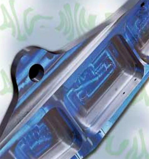
Milling is a material-removal operation. Any responsible manufacturing company devotes significant time to the optimum investment in modern CNC machine tools for those jobs at hand and to come. Equal amounts of time and focus need to be paid to choosing the right cutting tools that will maximize process productivity. Much like how custom tires on a high-end sports car ensure a peak driving experience, the cutting tool is the main interface between your machine and your work material. Determining a machining center’s maximum metal-removal efficiency depends in large part on the cutting tool selected and the machining parameters employed.
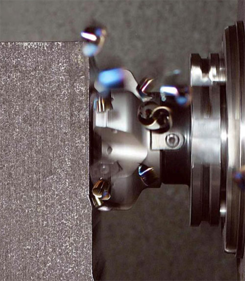
At its most basic, milling is the meeting of a rotating tool with a clamped and stationary workpiece, as opposed to turning where the tool is stationary and the work material rotates. Actually, the workpiece has feed motion imparted from the machine tool. The meeting of the rotary motion of the cutter and the cutting edge of the tools produces fluctuating cutting forces: vibration, heat, and, if all goes well, chips.
Historically, the ability to select all the proper variables necessary for a successful milling operation has been considered an art form. Machinists were toolmakers. They were given the specifications for making a part and often they had to create or modify their own tools to do so. This required metallurgy knowledge and long experience working with different types of materials. To perfect their craft, machinists were trained for manual skills, followed by years of trial-and-error learning about machinability. Such learning often took the form of tribal knowledge, rigidly guarded as “our way of doing things” and not easily transferred to others.
Today, tooling manufacturers abound with extensive, high-tech product lines for ever-expanding applications and tasks. Machinists still must learn about selecting the proper variables to ensure a successful milling operation, but tooling technology vendors are much more valuable as partners in increasing their knowledge.
Categories of Milling
Milling machines may have either vertical or horizontal spindle orientation, and typically, face milling cuts flat surfaces, but multi-axis CNC machines make it possible to include three-dimensional movements. That said, there are four basic categories of milling: face milling, periphery milling, slot milling, and specialty applications.
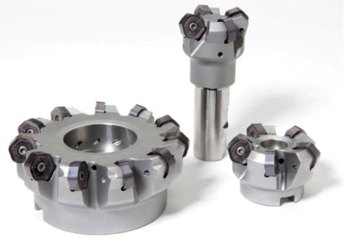
Face milling is used for creating a flat surface (face) on the workpiece. The cutting plane is usually perpendicular to the axis of rotation and the cutters most often feature a single row of inserts, designed with a wide range of cutting geometries, inserts, lead angles, and mounting adaptations. Surface finish requirements are an important input to determine the best tool type. Typically, face milling is performed by tools offering a lead angle for long tool life and reduced chance of breakout when exiting the workpiece.
Periphery milling generates a primary surface parallel to the spindle rotation. A secondary surface is sometimes produced. The cutting plane is usually parallel to the axis of rotation. Periphery milling cutters can be high-speed steel, solid carbide, or indexable-insert-based. Insert-based cutters may include one or more rows of inserts and may produce a simultaneous face-milling operation.
Slot milling is used for producing a slot or channel in the workpiece. There are two primary types of slot milling cutters: disk mills and end mills. Disk mills can be high-speed steel, brazed carbide, and indexable-insert-based. They are typically used in operations perpendicular to the spindle rotation.
End mills used for slot-milling operations are similar to the tools used in periphery milling. The slot being generated is parallel to the spindle rotation. However, because of full engagement in the periphery, poor chip formation, and evacuation, end mills are not a first choice for slotting operations.
While very versatile, end mills are the least stable of all milling cutters due to the smaller tool diameter and greater length. The diameter is the weakest portion of the tool because of the high tangential forcesdirected across it.
Specialty applications include copy milling, plunge milling, ramping, helical and circular interpolation, trochoidal, and others.
· Z-axis plunge milling is commonly used for removing large amounts of workpiece material. Cutting forces are directed into the cutter axially for higher metal-removal rates with long reach capability. The cutting plane is perpendicular to the axis of rotation.
· Ramping creates an angled surface on the workpiece or is used at the point of entry for making a pocket (pocketing). Compared to plunging, ramp milling may be less productive depending on conditions. This is also a common application requirement for pocket milling from a solid workpiece.
· Helical and circular interpolation is commonly used for creating a cylindrical surface on the workpiece, or for creating entry points for later applications. This application does not necessarily require an existing hole, depending on the type of tool chosen.
· Copy mills, such as round insert and high feed tools, are a common choice for these applications. The surface is typically parallel to the axis of rotation.
· Trochoidal milling is an application that typically produces a slot in difficult-to-machine materials. It uses a combination of periphery milling and circular interpolation in the X and Y planes.
Multiple operations can often be achieved by the same tool to reduce number of tools required and also tool changeover time, but can also require sacrifices in overall performance of a dedicated tool type, so understanding all required applications will allow you to make an informed choice.
Fundamental Considerations
Milling cutter selection is much more complex compared to other metalcutting processes. There are many variables involved. Primary among them are work material, machine tool size and horsepower, workpiece fixturing and rigidity, part design considerations, and overall process requirements.
All these variables are inputs that affect the design of the cutter to be used and the related application techniques, discussed more fully in the next article.
Glossary of Milling Terms
arbor milling A type of milling operation that uses a milling cutter mounted on a horizontal arbor.
arc of the cut The area of contact between the insert and the workpiece.
axial cutting force A primary cutting force that occurs parallel to the axis of the rotating tool. Both radial and axial forces constitute approximately 10 percent of the total cutting forces.
axial rake The angle formed by the tool axis and the incline of the face of the insert.
chip load Thickness of the chip. Chip load is often confused with IPT, but they are two separate variables.
clearance angle The angled relief behind the cutting edge that eliminates interference between the cutting tool and the workpiece.
climb milling A milling application in which the cutter rotation is in the same direction as the feed at the point of contact. Climb milling tends to pull the workpiece into the cutter, which decreases feed forces and power consumption.
coarse-pitch cutter A cutter containing a small number of inserts.
conventional milling A milling application in which the cutter rotation is in the opposite direction of the feed at the point of contact. Conventional milling pushes against the workpiece, which increases feed forces and power consumption.
copy mills Cutters used for 3D face milling with design characteristics that allow axial cutting depths that are greater than the length of the insert.
copy milling A face milling application designed to produce contoured or nonlinear surfaces or features into the workpiece.
cutter diameter The overall diameter of the cutter body. The appropriate diameter depends upon workpiece extensions and fixturing.
double negative rake angle Negative rake angle geometry that allows for good radial chip flow, but chip flow can be restricted.
double positive rake angle Positive rake angle geometry that allows for good chip lift. However, at high speeds the chips can get caught and re-cut by the insert.
effective diameter The maximum flat width of face that a cutter will machine. The effective diameter is measured at the outer cutting edge points of the insert.
end milling A type of milling in which a narrow cutter is used to machine surfaces both parallel and perpendicular to the spindle axis.
face clearance The angled relief behind the cutting edge that eliminates interference between the cutting tool and the workpiece.
face mill adapter A type of spindle mounting adaptation that is used for mounting and driving face mills on machining centers.
face mill cutter Cutters used for general face milling that are designed for 2D machining of flat surfaces perpendicular to the orientation of the spindle.
face milling A type of milling in which the workpiece surface is perpendicular to the spindle axis.
feed per tooth The linear distance traveled by the cutter during the engagement of a single cutting tooth. Feed per tooth (fpt) is the feed measurement for multiple cutting edge tools.
fine-pitch cutter A cutter containing a large number of inserts.
flat back drive A type of spindle mounting adaptation that is directly mounted to the spindle using a centering plug for radial location. Flat back drive is common for face mills over 8.00 inches in diameter and large special-purpose milling machines.
general face milling A type of milling in which the workpiece surface is perpendicular to the spindle axis.
hand of cut The direction of the cut. Left-handed milling cutters cut counterclockwise and right-handed cutters cut counterclockwise.
heel of the insert The edge of the land opposite the cutting edge.
helical interpolation A cutter which rotates about its own axis together in an orbiting motion about an ID or OD workpiece circumference.
high-density cutter A cutter containing a large number of inserts per inch of diameter.
insert density The number of inserts, or cutting edges, per inch of diameter in a mill. Also referred to as cutting edge density.
insert facet A device used in milling inserts to reduce or eliminate the surface finish problems created by axial variation in face milling cutters.
insert pitch The number of inserts in a cutter. Pitch is the distance between corresponding positions on one insert to the same position on the subsequent insert.
IPT Inch per tooth. The increment of feed that one insert makes in one revolution of the cutter. Referred to most commonly as “fz.”
lead angle The approach angle of the cutting edge as it enters the workpiece. The lead angle controls the direction of the radial and axial cutting forces.
low-density cutter A cutter containing a small number of inserts per inch of diameter.
milling A metal cutting process that uses a rotating multi-point cutting tool to machine flat surfaces, slots, or internal recesses into a workpiece.
mounting adaptation The specific design of tooling and components used to secure the milling cutter to the machine tool.
negative axial rake Rake geometry indicating that the cutting edge is positioned on the axial centerline of the cutter while the top surface of the cutting edge slopes forward and away from the axial centerline.
negative radial rake Rake geometry indicating that the cutting edge is positioned on the radial centerline of the cutter. The top surface of the cutting edge slopes forward and away from centerline of the cutter.
neutral axial rake Rake geometry indicating that the cutting edge is positioned on the axial centerline of the cutter with the top surface of the cutting edge sloping back and away from the axial centerline.
neutral radial rake Rake geometry indicating that the face of the insert lies on the radial centerline of the cutter.
nose radius The radius on the tool between the end and side cutting edges.
periphery milling A type of milling in which the surface of the workpiece is perpendicular to the machine spindle while the cutter is mounted on an arbor.
positive axial rake Rake geometry indicating that the that the cutting edge is positioned on the axial centerline of the cutter with the top surface of the cutting edge sloping back and away from the axial centerline.
positive radial rake Rake geometry indicating that the cutting edge is positioned on the radial centerline of the cutter. The top surface of the cutting edge slopes back and away from the radial centerline.
positive/negative rake angle Rake angle geometry that gains the benefits of both double positive and double negative rake angles without the problematic features of either.
radial cutting force A force tending to push the tool away from the workpiece in the radial direction. Both radial and axial forces constitute approximately 10% of the total cutting forces.
radial rake The angle formed by the incline of the face of the insert and a radial line passing through the cutting edge in a plane perpendicular to the cutter axis.
ramp milling A combination of Z-axis movement simulataneous with X, Y, or combined axis movement.
rake angle The incline of the top surface of the cutting edge that makes contact with the chip. The rake controls the degree of cutting forces and cutting edge strength.
rake face build-up The pressure welding and accumulation of workpiece material onto the rake face of the tool.
ramp milling An advanced form of 3D face milling.
shell mill adaptation A type of spindle mounting adaptation designed for face milling cutters from 1.5 to 6 inch diameters. Shell mill adapters contain a central pilot, radial keys, and a central bolt for securing the cutter to the adapter.
side milling A type of milling in which the surface of the workpiece is perpendicular to the machine spindle while the cutter is mounted on an arbor.
slot milling A type of milling used to produce a slot or channel.
square shoulder mill cutter Cutters used for square shoulder milling with a 90-degree lead angle. Feed forces for square shoulder face mills occur in the radial direction.
square shoulder face milling A type of milling that is designed to perform the operations of both a face mill and an end mill.
surface finish pattern The measured surface profile characteristics of a workpiece. The most important variable for surface finish is roughness.
tangential force A force acting on the tool's rake face in the direction of the cutting velocity. Tangential cutting forces represent a resistance to tool rotation and constitute approximately 70 percent of the total cutting forces.
trochoidal milling An advanced form of 3D face milling that uses high-speed machining technologies. Trochoidal milling minimizes changes in the chip load and achieves high and constant feed rates and most commonly employs a low radial depth of cut with high axial depth of cut.
true rake angle The accumulation of rake angles on a given metal cutting application. Also expressed as TRA.
variable-pitch milling cutter A cutter with unequally spaced inserts, which is used to reduce vibration or chatter.
Editor’s note: You can read the next part by clicking here.