


QIF is an interoperability standard that provides a common communication language for information about characteristics specified for discrete parts. QIF, or the Quality Information Framework, is important because it adds to the digital conversation that must run uninterupted through the entire manufacturing process, from product design to production to inspection, and even beyond to the product’s end-use performance. The result of this ongoing, back-and-forth dialog about quality will be goods that last longer, cost less, perform better and are safer for users and the environment. QIF truly gives new meaning to the old saying, “We measure to improve.” Here’s why.
Standardization for Digitalization
Perhaps the main benefit of QIF is that it fills a gap needed to implement Industry 4.0 or data-driven manufacturing, concepts that envision the complete integration of manufacturing through digitalization. Digitalization simply means that vital information is turned into digital data formatted to be used by computers, typically connected to other computers on a network. However, digitalization cannot go very far, or work as well as it should, if the digital format of the data is not standardized for interoperability and exchangeability.


Interoperability indicates that data from one system can be read and processed by another system so that their efforts are coordinated. This makes it easy to interface computerized machines and devices on the shop floor. Exchangeability indicates that data has the same meaning and can be interpreted unmistakably when shared between software applications. This avoids problems that can occur when data from one system must be translated or reformatted so another one can interpret it. During this extra step, the meanings of data elements and the values of numbers sometimes can change, leading to confusion or calculation errors.
The purpose of QIF is to provide interoperability and exchangeability for computer-generated data related to quality control in manufacturing. QIF is designed so that nothing “gets lost in translation.”
The need for a standard such as QIF has long been recognized by the metrology wing of the manufacturing community. This awareness led to the formation of the Digital Metrology Standards Consortium (DMSC) in 2006. Its charter is to develop urgently needed standards to advance dimensional metrology. This consortium consists of member organizations representing providers and users of metrology systems in manufacturing, along with government and academic institutions. The most recent version of QIF (3.0) was released as an approved American National Standards Institute (ANSI) standard in February 2019 and currently is being promoted as an ISO standard.
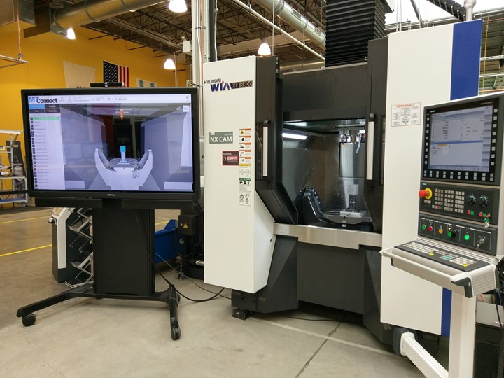
In a demonstration arranged by Step Tools (Troy, New York) the digital twin of a part being machined on a Hyundai Wia machining center were measured for quality assurance during the metal removal process. The results from measuring the digital twin could be displayed in real time, viewed remotely across a network and acted upon to ensure that the part met dimensional tolerances and other specified characteristics. QIF data models were an essential enabler in this scenario.
Robert Brown, vice president-operations at Mitutoyo America, explains why QIF is important to both users and providers: “Our customers want interoperability because it enables them to choose best-of-breed systems for deployment in their manufacturing operations. As a solution provider, these standards allow us to concentrate on our core competencies instead of developing interfaces to other proprietary systems.”
Inside QIF
At its core, QIF is a library of data models that addresses how quality data is used at different times and for different functions in the design, production and inspection of discrete parts. For each of these uses of quality data, QIF provides an information model as an XML (eXtensible Markup Language) schema that specifies standardized terms, meanings and usage rules along with rules for how information is ordered and arranged as required by the application.
For example, one of these information models is called QIF-Results. It covers how measurements taken by metrology devices should be presented so systems that need these results can read them. Ideally, all metrology devices will be able to give measurement results following the QIF-Results information model, and all systems will be able to read these results for processing.
Sharing measurement results without translators or reformatting of data is certainly a case in which a QIF schema is obviously needed and beneficial. However, QIF includes five additional application areas in which standardized information models make quality data exchangeable for system interoperability: QIF-MBD (Model Based Definition), QIF-Plans, QIF-Resources, QIF-Rules, QIF-Results and QIF-Statistics. (See Table 1.)
All of these application areas are practical and intuitive. QIF-Plans, for example, provides another essential information model that machine shops will find useful. In this case, QIF-Plans enables a CAD model in which Product Manufacturing Information (PMI) is embedded so that it can be rendered as a bill of characteristics. This saves time and improves accuracy in developing inspection programs.
Together, the QIF schema can be said to represent start-to-finish, step-to-step coverage of the entire quality control process from design to analysis. This makes QIF a truly integrated, comprehensive framework.
|
Table 1. The Quality Information Framework Library of Data Models |
|---|
|
QIF MBD (Model-Based Definition) — A structure and format for integrating the computer-aided design (CAD) file and product manufacturing information (PMI). |
|
QIF Plans — A structure and format for a bill of characteristics (what must be measured) and measurement plans (how the characteristics are to be measured). |
|
QIF Resources — A structure and format for defining the type of metrology device suitable for the measurement task. |
|
QIF Rules — A structure and format for creating measurement templates, developing macro measurement routines and defining best practices. |
|
QIF Results — A structure and format for capturing and reporting measurement data from metrology devices to be read by systems. |
|
QIF Statistics — A structure and format for statistical process control using QIF data |
Another key benefit is that the QIF MBD (Model Based Definition) lends itself to interpretation by graphical CAD systems so that 3D digital models of the actual part can be created for viewing as a screen image or for downloading to applications requiring the model for analysis and comparison.
Thus, QIF takes its place alongside other interoperability/exchangeability standards useful for integrating the entire manufacturing process. For today’s machine tool users, the two most important standards that QIF can interact with are ISO AP242 and MTConnect.
Importance of Data Interaction
ISO AP242 is the interoperability standard for data about the original part design as a digital model. This is essentially the 3D CAD file representing the part shape along with details about tolerances and other information needed for manufacturing. ISO AP242 is part of the STEP (STandard for the Exchange of Product model data) family of standards for exchanging data about physical parts and mechanical structures. STEP is the successor to IGES, the Initial Graphics Exchange Specification, one of the earliest standards to enable CAD systems to exchange design files.
MTConnect is the interoperability standard for data from machine tools and other computerized production equipment. MTConnect has made it easier to connect machine tools to accessories and auxiliary equipment such as bar feeders, robotic loaders and unloaders and other types of automation. More significantly, MTConnect has proven instrumental in making machine data collection feasible for machine performance monitoring, analysis and reporting.
MTConnect has succeeded because it is an open-source standard that communicates machine-generated data as a common language in an internet-ready format. This format is XML, which is almost universally used for data being shared across the internet and saved in databases accessible to software programs. MTConnect is useful for capturing and sharing process data — digital information about what a machine tool is doing as it is making parts.
QIF is also an open-source standard that translates metrology data into a common language in XML. QIF is useful for capturing and sharing product data — digital information about a part’s physical characteristics such as its dimensions, geometric shape and appearance.
Although ISO AP242, MTConnect and QIF are continually being refined and enlarged, current releases are complete enough that together, they cover the core elements of manufacturing — design, production and inspection. These three standards are, for the most part, compatible and complimentary. Early demonstrations of such standards working together promise to optimize and streamline manufacturing on a new level.
Because the digital twin of a workpiece is digital, it can be analyzed by software, displayed for viewing and shared with remote decision-makers. Because it is a twin — an identical stand-in for the physical object — information about it, such as measurement results, is as valid and actionable as information derived from the actual workpiece.
Simply stated, ISO AP242 tells us what we want to make: the ideal part. MTConnect can tell us how we made it: the real part. And QIF can tell us how close the real part is to the ideal part. By combining this information in a computer system, we can find insights into the “whys” that have been hard to come by in manufacturing. For example, why is this machine or process putting out parts that “don’t meet specs?” Answering questions like this and finding a solution is ultimately what developers of these standards are shooting for. The fix might be a better design, a better part program, a better cutting tool, a better axis drive — some change indicated by verifiable and timely information. Moreover, it might be possible to execute this change automatically.
For example, results of software programs using QIF data can be reported back to manufacturing to create a feedback loop. Statistical analysis of this reported quality information might detect excessive variation in a critical dimension and trigger a corrective action. However, QIF enables a feedback loop to go beyond what is possible in, say, a closed-loop machining system, which you can learn more about watching a webinar at gbm.media/mituto1117.
Broader, Deeper Feedback Loops
Typically, closed-loop machining is limited to an application on a single machine or machining cell, whereby quality trends can be monitored so machining parameters can be adjusted (or the process stopped) in time to prevent making parts that must be scrapped or reworked because they exceed allowable deviations specified in the part design. Although QIF supports such a closed loop in production settings, QIF enables quality information to flow upstream to more advanced software technology, such as machine learning or big-data analysis.
An example of machine learning is a system that automatically evaluates a strategy for avoiding quality defects by adjusting several interrelated variables such as compensating for tool wear by changing tool offsets along with adjustments to speed, feeds or stepovers in tool paths. Big data analysis can take this example one step further by studying the effectiveness of many different strategies reported by multiple users to find insights into root causes such as an inherent weakness in the structural configuration of a certain model of machine tool or a sub-optimal arrangement of indexable inserts in a certain style of cutter. The point here is that QIF helps move quality control from detecting problems to identifying and resolving underlying sources of problems. To be clear, researchers are just scratching the surface of these possibilities today.
QIF provides interoperability and exchangeability for computer-generated data related to quality control in manufacturing.
It is also important to point out that QIF is being structured to handle one of the most challenging aspects of quality information systems, that is, how to get quality information to follow an individual workpiece while it is still progressing through the various stages of the manufacturing process, and then moves along the value chain as it becomes a component in a completed assembly. Also part of this challenge is keeping quality information related to the performance of the part in the final product when it reaches the consumer or end user.
To meet this challenge, QIF will specify the format for a unique universal identifier (UUID), which will most likely be a long string of hexadecimal code. The concept is to have this UUID as a “persistent identifier.” That is, one that can be carried from system to system as the digital code name for an individual part or even a certain part feature. This code name can then be associated with pertinent quality data stored in local or remote data bases to be called up when needed. In other words, individual parts and related quality information will not be able to lose track of one another. It may be helpful to think of the UUID as a kind of Social Security Number for a workpiece. Meeting requirements for part traceability in the aerospace industry is one area where this development would be a benefit.
An Identical Stand-In
The significance of having QIF and similar interoperability standards such as MTConnect and STEP AP242 might become clearer by examining their convergence in the realization of concepts such as the digital thread and the digital twin. Most often, “digital thread” implies that computer-interpretable data will convey information associated with workpieces and operations throughout the entire manufacturing, much like a thread that can be followed through a woven fabric.
The general usage of the term ‘digital twin’ seems to be looser, making its meaner harder to pin down. However, recent demonstrations involving computer models to serve as virtual stand-ins for physical parts are solidifying the digital-twin concept, as least in the context of CNC machining and product inspection.
One of these demonstrations, the so-called Grand Challenge conducted at the 2018 International Manufacturing Technology Show (IMTS), is particularly revealing not only because the practical value of the digital twin in manufacturing came across, but also because QIF, MTConnect and STEP AP242 were proven to be instrumental in enabling the digital-twin concept to work as intended. Here is a summary of what happened at the Grand Challenge as it relates to the role of the digital twin.
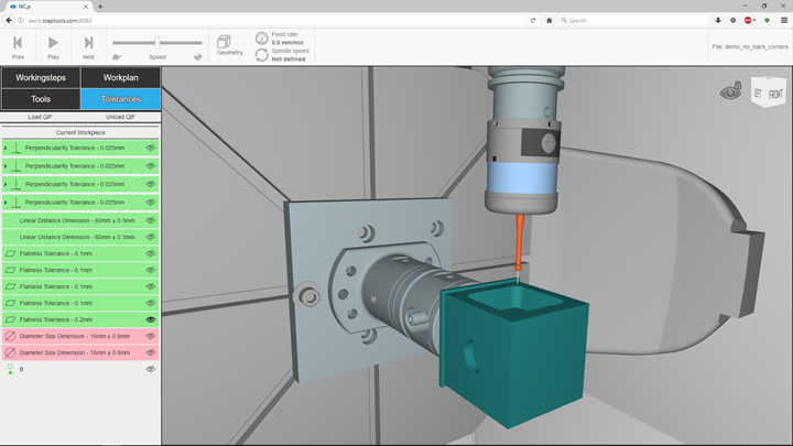
While a test workpiece was being machined on a five-axis machining center in one exhibitor’s booth, observers could watch a large display screen to see a real-time graphical representation of the virtual workpiece undergoing the same changes in size and shape that were being produced by the tool path of the cutting tool on the machine. What was happening on the display screen corresponded to what was happening on the machine. This correspondence was so exact and timely that numerical values for dimensions derived from the part on the screen could substitute for dimensions of the actual part on the machine.
The graphical simulation program creating the screen display analyzed these dimensions to color-code the virtually machined part features as being in tolerance (green), out of tolerance (red) or in the warning zone (yellow). This information could be used to make decisions about the process with the expected results being the same as if based on physical measurements of the actual part. An obvious advantage here is that these decisions would otherwise require stopping the machine or moving the part to an inspection station. This is possible because the virtual part was an identical stand-in for the physical workpiece. It was, in fact, a digital twin of the real part.
In the demonstration at IMTS 2018, the digital twin served other functions. For example, after roughing operations were completed on the test part in the original machine at the original booth, the physical part was moved to a different five-axis machining center in another machine tool builder's booth at the show. The data file of the rough-machined digital twin was loaded into the new machine’s CNC and used to update tool paths in the existing part program. Finishing passes were then successfully executed to complete the part on the new machine in the new booth. During these operations, the same graphical simulator running in this booth displayed the virtual results for observers who had moved there to witness the conclusion of the demonstration. The demonstration’s success was impressive because this seamless relocation of a production job in the real world would be very difficult to accomplish.
In a nutshell, here is how this successful demonstration of the virtual twin in action came about. The original 3D part design model was created in the STEP AP242 format, in which geometric dimensioning and tolerancing (GD&T) was embedded. This model could be downloaded and interpreted by all of the machines, devices and systems used in the demonstration, including the different CAM programming software, the machining centers in the two exhibitors’ booths, the graphical simulator and the metrology equipment used to duplicate or verify inspection results.
Live streaming of machine data to the simulator was possible with MTConnect. This enabled the simulation to replicate how actual machine motions and tooltip locations were altering the part model in real time. The apparent changes in size and shape could be read into metrology analysis software and the results transmitted as QIF data to the simulator for the color-coded display and to on-machine probing systems and offline CMMs to create inspection programs that verified machining results. (Learn more about the Grand Challenge at gbm.media/gc.)
Will You Be Ready?
What QIF and other interoperability standards promise is the complete digitalization of manufacturing. The ability to move data across networks that connect machines for greater automation, connect people for greater collaboration and connect computers for greater integration is the “big picture” that requires visualization right now.
Consider this scenario: A major defense contractor comes looking for a machine shop to complete 50 large aerospace workpieces to fill a 300-piece order that another subcontractor started but is now unable to finish on time. The shop ready for digital-twin manufacturing will have the advantage, because it will be able to pick up the pieces where the other contractor left off and get the job done in a timely and precise manner.
In the meantime, the organizations responsible for developing interoperability standards needed for data-driven manufacturing continue to work on the remaining technical challenges such as completing extensions for added functionality and preparing for the enhanced broadband capability of the next generation (5G) of wireless networking. As efforts of the developers progress, so will the new era of digitalized manufacturing.


Related Content

Determining Out-of-Roundness at the Point of Manufacture
George Schuetz, Mahr Inc.’s Director of Precision Gages, offers these techniques for measuring roundness on the shop floor.
Read More
A Case for Combining Workholding with Optical Scanning
Automotive dies and die inserts are often complex, one-off parts with little room for error. Integrity Tool's investments in modular workholding tools and 3D optical scanning have allowed the company to create niche capabilities for its CNC machined parts.
Read More
5 Things CNC Operators Must Know About Sizing Adjustments
For CNC operators, sizing adjustment is an essential skill. Keep these points in mind when training new CNC users.
Read More
Choosing the Correct Gage Type for Groove Inspection
Grooves play a critical functional role for seal rings and retainer rings, so good gaging practices are a must.
Read MoreRead Next

The ISO 13399 and MTConnect Connection
These two data exchange standards work together to promote the concept of data-driven manufacturing. Both standards will help shops make better decisions about shopfloor activities.
Read More
Understanding MTConnect Agents and Adapters
MTConnect agents and their corresponding device adapters are simply small computer programs that work together so that MTConnect can make shop equipment and networks more readily connectible. In a nutshell, adapters enable existing shopfloor devices “to speak MTConnect,” and agents enable MTConnect messages and data files to be transmitted across a network to MTConnect-compatible applications.
Read More
ISO 13399—A Key Step Toward Data-Driven Manufacturing
Decisions about the cutting tools used in machining operations are arguably among the most important in modern manufacturing.
Read More