
Adaptive Machining For Turbine Blade Repair
Real-time-responding CNC brings new possibilities to difficult machining applications.


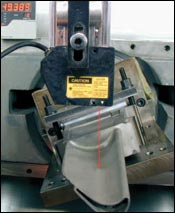
Blade and blisk repair using adaptive machining starts by scanning the component. Laser digitizing, which offers an alternative to traditional touch probes, is particularly effective for rapidly scanning large surfaces.
Adaptive machining automatically modifies programmed tool paths to cope with subtle part-to-part geometric variations encountered when repairing turbine engine components.
The term “adaptive machining” is widely used these days. In general, it describes a technology that adapts manufacturing data to suit changing conditions. Adaptive machining is typically used when individual components in a batch have slight geometric differences. These components often require blending and/or polishing operations that count on the skill and dexterity of the human hand.
Some systems that are said to be adaptive actually offer best-fit capability. That is, they align a workpiece to a known datum position. Truly adaptive machining technology addresses the specific variations that make one workpiece different from another. It uses a scanning system, special software and an attendant computer integrated with a CNC machine’s control to take executive control of the process, automatically modifying programmed tool paths to cope with subtle part-to-part variations.


Processes for manufacturing and repairing blades and vanes used in gas turbine engines are inherently suitable for adaptive machining. That’s because they pose a wide range of complex geometry-related challenges, often requiring five-axis machining strategies. That said, some repair operations such as airfoil recontouring following weld repairs are still performed manually. This is why the gas turbine industry is a main focus for TTL, a UK-based company that has been designing and delivering custom adaptive machining systems for nearly 20 years. TTL is part of StarragHeckert.
An Adaptive Example
A demonstration that TTL performs to illustrate the capability of adaptive machining technology is a five-axis engraving
operation on the surface of uncooked chicken eggs. Like the blades, vanes and combustion components that make up modern gas turbines, no two eggs are identical.
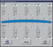
The first step is to digitize the egg’s surface. The captured data is transferred to a computer that processes the data and models the egg’s size and shape. Machining tool paths unique to a particular egg are generated based upon that data. The resulting NC code controls the five-axis machine and allows it to engrave the egg’s shell at a pre-defined depth of approximately 0.05 mm (0.002 inch) regardless of surface variations.
The challenges in engraving different eggs are technically equivalent to machining new castings or forgings and removing the coatings or excess weld when repairing turbine components. Good results can be achieved with the appropriate combination of fixture design, type of machine tool and machine tool setup. For repaired turbine components, for example, blend accuracy between repair weld and parent material with a step size as small as +0.00 mm/+0.02 mm (+0.000 inch/+0.0008 inch) can be achieved.
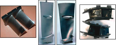
Adaptive machining technology is also effective in repairing blisks (bladed disks). The one-piece blisk design replaces the traditional series of individual blades that make up the stages of a rotor. Blisks have become widely integrated into rotor designs in recent years because they offer significant performance advantages over single-blade designs. Blisks are primarily produced using five-axis machining operations to achieve the required cycle times, accuracy and surface finish. They are more expensive and complex to manufacture than single-blade designs, so there is significant interest in developing cost-effective methods to repair them. However, their complex geometries make the blisk repair process equally as difficult as manufacturing new ones.
Repair is necessary when a blisk becomes physically damaged in service (from a bird strike, for example) or due to routine wear. Blisk repair often starts by building up the airfoil surface at the tip and leading edge or completely replacing individual airfoil sections via electron-beam welding. In either case, the added material must be contoured to bring the airfoil surface back to its original shape. Using adaptive machining, operations such as chord restoration, leading-edge profiling, airfoil surface machining and blending back into the original material can be performed automatically.
In addition, blend accuracy can often be achieved without compromising component thickness or geometric form. This is particularly important in stress-critical turbine applications in which wall thicknesses must be maintained. Although manual blending may produce a component that’s cosmetically pleasing, the component’s geometric accuracy may not meet specifications.
It Starts With Scanning
Touch probes or laser scanning probes allow the adaptive machining process to account for plastic deformation and worn components prior to machining. Compared with touch probes, the speed with which a laser can capture data provides a dramatic reduction in scanning times. This is particularly helpful in situations when large surfaces need to be recreated rapidly and efficiently, such as the repair of gas turbine components. TTL’s LDS–100 system uses a laser digitizing head that installs in the machine’s spindle as well as a high-speed computer interface card. Data gathered from the device are captured directly into a high-speed, analog-to-digital converter in the attendant computer. Data points can either be captured individually or continuously streamed at speeds as fast as 100,000 points per second, which translates to digitizing speeds as fast as 6 meters per minute.
The laser is supported by custom software routines for data conversion, filtering and smoothing. Laser scanning can produce results to ±0.005 mm.
Machine Requirements
For adaptive machining applications, the machine’s CNC must offer an open architecture to allow two-way communication between the control and attendant computer. This communication must consist of more than just program uploading and downloading. For instance, the adaptive system should be able to determine from the machine the status of cutting tools in the carousel and also to read and react to machine error messages.
Two-way communication is also necessary to allow adaptive polishing using polishing and grinding media. It is important to keep track of the actual wheel size, which changes with wheel wear and dressing. This is done via in-process laser measurement controlled by a low-level communications interface between the attendant computer and CNC.
Because the faster computing power now available provides the ability to process large amounts of data quickly, the complex computations that are required for adaptive machining can be performed virtually in real-time. In addition, the latest CNCs provide the high processing speeds necessary to handle complex five-axis machining data even at high feed rates.
About the author: Paul Walton is the managing director for TTL, based in Haddenham, Bucks, UK.


Related Content

10 Tips for Titanium
Simple process considerations can increase your productivity in milling titanium alloys.
Read More
Modern Bar Feeds Bring New Life to Automatic Swiss Lathes
Cam-actuated Swiss lathes are still the fastest way to process many parts. By adding modern bar feeders, this shop has dramatically improved their utilization with the ability to work unattended, even in a lights-out environment.
Read More
SolidCAM Wants to Help Machine Shops Get into Additive Manufacturing
SolidCAM's partnership with Desktop Metal is aimed at making additive manufacturing more accessible to job shops and other manufacturers.
Read More
10 Things to Know About Creep-Feed Grinding
Because of the high material removal rate creep-feed grinding can deliver in challenging materials, grinding might not be just the last step in the process—it might be the process.
Read MoreRead Next

Blade Grinding’s Need For Speed
A grinding technique akin to high speed machining offers an alternate method for grinding nickel-alloy blades and vanes used in turbine engines.
Read More
3 Mistakes That Cause CNC Programs to Fail
Despite enhancements to manufacturing technology, there are still issues today that can cause programs to fail. These failures can cause lost time, scrapped parts, damaged machines and even injured operators.
Read More
