
Are Two Ballscrews Better Than One?
A dual ballscrew arrangement on the Z axis leaves the middle of the base open for chip evacuation, solving the problem on table feed Z-axis, horizontal machining centers.


The ability of the Fanuc 16i to synchronize the dual ballscrew motors makes its use practical. This technology is applied on the Y axis to eliminate the need for a spindle carrier counterbalance.
This drawing shows the difference in area for chip evacuation between a conventional horizontal machining center and the new design from Toyoda.
A dual ballscrew arrangement on the Z axis allows Toyoda to create a through-hole in the center of the machine base for direct chip evacuation. A rear exit chip conveyor slides under the base and catches the chips as they drop.
Efficient chip evacuation from horizontal machining centers is a headache for most shops. In general, efforts to automate chip removal often involve augers and flush systems designed to move chips along the outside edges of the work zone and eventually out of the area into a chip conveyor for disposal.
Toyoda Machinery USA (Arlington Heights, Illinois) has come up with what it feels is a good solution to the chip evacuation problem on table feed Z-axis, horizontal machining centers.


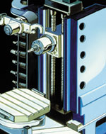
Most HMCs of this type use a configuration composed of a set of ways running along the side of the Z axis base structure with a ballscrew centered between them. In this design, use of the middle of the base structure for chip evacuation is precluded because the ballscrew passes through it. Therefore chips must be pushed to either side of the base for evacuation. The way covers and ballscrew covers are pitched, like a roof, to help direct the chips to the sides of the base. From there they are moved with augers or washed to a chip conveyor.
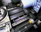
What Toyoda has done is create a center through-hole base so chips fall directly into a large capacity chip conveyor that exits the rear of the machine. The chip conveyor slides under the machine base occupying the space between the ways.
So where’s the ballscrew? Actually there are two ballscrews on this design. In order to balance the movement of the Z-axis carrier, a ballscrew is located on the right and left sides of the carrier parallel to the ways. This leaves the middle of the base open for chip evacuation.
The enabling technology for this design is a feature on the Fanuc 16i CNC called tandem control. This allows the dual axis ballscrews to perform in synchronized fashion so one or the other can’t try to skew the work table carrier.
In operation, one of the two identical AC servomotors driving the ballscrews functions as the “master,” and the other is the “slave.” The master motor controls the axis movements, while the slave motor follows.
Parallel performance is monitored and adjusted by the CNC, which reads the electrical current of the slave motor. If the current of the slave motor goes up, a signal from the control is sent so the slave self-adjusts to compensate. Synchronization is maintained.
At start-up, the Z axis is automatically “homed” using the master motor’s absolute position encoder, and the slave motor is synchronized off this position. Generally, no further mechanical alignment or adjustment is necessary between the two motors. However, should the machine need to be reset, homing the master axis drive will automatically re-synchronize the motors.
Toyoda has also applied dual ballscrews, in combination with the Fanuc 16i tandem control feature on the Y axis of its FA 800 horizontal machining center. In this case, the dual ballscrews eliminate the need to counterbalance the spindle carrier. The load of the carrier is shared between the two ballscrews, which, the company says, increase responsiveness of the axis for high-speed acceleration and rapid traverse rates.
If one ballscrew is good, two are better? That seems to be the case on these machining centers. MMS


Related Content

How to Reduce Cycle Times by 70% and More on Your Existing CNCs and Dramatically Improve Tool Life Too
By employing advanced high efficiency milling techniques for the entire machining routine, SolidCAM’s iMachining technology can drastically reduce cycle times while vastly improving tool life compared to traditional milling.
Read More
Volumetric Accuracy Is Key to Machining James Webb Telescope
To meet the extreme tolerance of the telescope’s beryllium mirrors, the manufacturer had to rely on stable horizontal machining centers with a high degree of consistency volumetric accuracy.
Read More
Grinding Wheel Safety: Respect The Maximum Speed
One potential source of serious injury in grinding comes from an oversight that is easy to make: operating the wheel in an over-speed condition.
Read More
A New Milling 101: Milling Forces and Formulas
The forces involved in the milling process can be quantified, thus allowing mathematical tools to predict and control these forces. Formulas for calculating these forces accurately make it possible to optimize the quality of milling operations.
Read MoreRead Next

The Cut Scene: The Finer Details of Large-Format Machining
Small details and features can have an outsized impact on large parts, such as Barbco’s collapsible utility drill head.
Read More

3 Mistakes That Cause CNC Programs to Fail
Despite enhancements to manufacturing technology, there are still issues today that can cause programs to fail. These failures can cause lost time, scrapped parts, damaged machines and even injured operators.
Read More