
Average Chip Thickness Dictates Milling Performance
Attaining the correct average chip thickness for a particular insert should be a chief goal in any milling application. Here's an explanation of what that term means and why it's important.

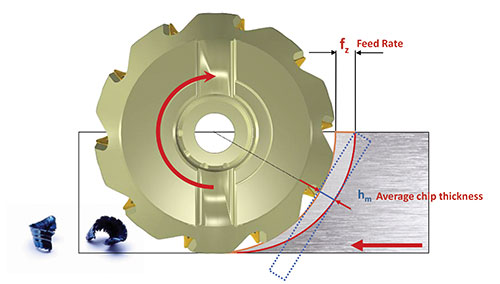
Unlike turning, milling generates chips that vary in thickness according feed rate, the percentage of the tool diameter engaged in the cut, and the inserts’ edge preparation and lead angle. Average chip thickness is calculated from the size of the undeformed chip at right angles to the cutting edge.
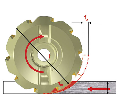
Note that the chip in this diagram is less thick than the chip in the diagram above. That's because less of this tool's diameter is engaged in the cut.
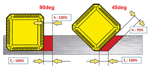
As shown here, a lower lead angle spreads the cut over a longer section of the cutting edge. However, feed per tooth must be increased because the chipload is smaller.


The first cut in this video is a full slotting application—that is, 100 percent of the tool diameter is engaged. Each subsequent cut reduces the tool’s engagement, yet the sound generated by the cutting action is virtually indistinguishable. That’s because cutting parameters have been set with the goal of maintaining the same average chip thickness regardless of radial engagement.
In any milling application, setting a feed rate that yields the correct average chip thickness for a particular insert is critical. Yet many manufacturers overlook this basic principle, says Todd Miller, manager of rotating products for Seco Tools. The typical result is unexplained problems with premature insert failure, poor surface finish, work hardening, vibration or deflection.
The key word here is “average,” Mr. Miller explains. Unlike turning applications, inserts on a rotating milling tool encounter different forces at different portions of the cut. (For example, the insert cuts progressively shallower and encounters progressively less resistance as it rotates out of the cut from full depth during climb milling.) The result is chips that are thicker on one end than on the other. Given that the very nature of the milling process makes it impossible to generate chips with a consistent thickness, the only option is to aim for an average. That average can be calculated from the size of the undeformed (uncut) chip at all points where the insert is oriented at a right angle to the workpiece. “If you could take a chip and lay it out flat, the average thickness would be right in the middle,” he says.


The ideal average chip thickness for a particular insert depends on the insert’s edge preparation. Compared to the sharp angle formed by the rake and flank faces of a typical turning insert, a milling insert’s cutting edge generally has a small chamfer to protect against the shock of repeated material entry. Chips should be at least as thick as this edge protection (typically in the form of a T-land or hone) to properly dissipate heat. Chips that are too thin indicate that the cutting action—and the heat it generates—is constrained to a relatively small portion of the insert edge. This can lead to premature cratering, thermal cracking or flank wear. Chips that are too thick indicate high cutting forces that could overwhelm and break the insert.
Seco lists the proper average chip thickness for a given insert in its standard product catalog. The user’s task is to arrive at the feed rate that yields that value. This rate depends on both the radial engagement of the tool (the percentage of the tool’s diameter engaged in the cut) and the lead angle of the insert (the angle formed between the insert’s outer edge and the center axis of the tool shank). The smaller the radial engagement, the larger the feed rate required to arrive at the proper thickness value. That’s because the thickest possible chip for a given tool is generated at the 50-percent-diameter mark, where the insert is buried in the material to the fullest possible extent. So, a cutter with less of its diameter engaged must move into the material at a higher rate to arrive at the same chip thickness as one that’s more fully engaged. For the same reason, calculating average chip thickness is generally not as valuable if radial engagement is greater than 50 percent, Mr. Miller adds. Consider that if the chip is thickest at the 50-percent-diameter mark, it will be thinner at any point beyond that. So, changes to radial engagement at any point above 50 percent make less difference on the average thickness of the chip. It follows that the feed rate adjustment required to compensate is also less significant.
The exception to this general principle relates to the other contributing factor: the insert lead angle. Similarly to radial engagement, the lower the lead angle, the higher the feed rate. Consider that at 90 degrees, the ratio of chip thickness to feed per tooth during a full slotting application (100 percent radial engagement) is 1:1—that is, the material removed by each insert on each revolution is equal to the width of the insert’s cutting edge. At a 45-degree lead angle, however, the chip thickness is only about 70 percent of the feed per tooth because the edge is slanted relative to the direction of feed. Thus, a user employing a facemill with 45-degree inserts at 100 percent radial engagement should know that this tool must feed approximately 30 percent faster than a shoulder mill to attain the same average chip thickness, Mr. Miller says.
Understanding the complex interplay of factors that drive chip formation is critical to understanding the importance of attaining the correct average chip thickness. Getting there, however, is relatively easy, at least with Seco inserts, Mr. Miller says. The company’s standard catalog features charts and formulas that help users arrive at the correct value for any given tool and insert combination.


Related Content

Five-Axis Changes Weldments Into Monolithic One-Piece Parts
Moving from welding to five-axis machining enabled Barbco to redesign its weldments as monolithic one-piece parts with improved strength and repeatability.
Read More
How to Mitigate Chatter to Boost Machining Rates
There are usually better solutions to chatter than just reducing the feed rate. Through vibration analysis, the chatter problem can be solved, enabling much higher metal removal rates, better quality and longer tool life.
Read More
New Modular Tool Options for Small Spindle Milling
Tooling options have been limited for small spindle milling applications. Now modular, indexable systems are available that provide broad flexibility to get the right cutter for the job with less inventory and at lower cost.
Read More
Twin Spindle Design Doubles Production of Small Parts
After experiencing process stalls in the finishing stage of production, Bryan Machine Service designed an air-powered twin spindle and indexable rotating base to effectively double its production of small parts.
Read MoreRead Next


3 Mistakes That Cause CNC Programs to Fail
Despite enhancements to manufacturing technology, there are still issues today that can cause programs to fail. These failures can cause lost time, scrapped parts, damaged machines and even injured operators.
Read More
The Cut Scene: The Finer Details of Large-Format Machining
Small details and features can have an outsized impact on large parts, such as Barbco’s collapsible utility drill head.
Read More