Loading the player ...
See both carbide and ceramic Excelerator end mills in action.
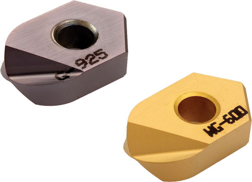
In early summer 2010, I had a long talk with Dale Hill, applications engineer at Greenleaf Corp., the cutting tool manufacturer in Saegertown, Pennsylvania. Greenleaf has a tightly focused yet innovative product line but doesn’t do a lot of splashy promotions to attract attention beyond its target markets. I was interested in the company’s new line of Excelerator ballnose end mills because the product descriptions hinted at some revealing insights into the nature of insert cutting action. The fact that the line includes both ceramic (WG-600 grade) and carbide (G-925 grade) inserts for the same cutter bodies intrigued me. Statements about the insert geometry preventing excess “tool pressure” also got my attention.
The discussion with Mr. Hill proved to be enlightening. The most important thing he clarified was the relationship between chip thinning, cutting speed and heat transfer. This relationship forms the theoretical basis for the effectiveness of the Excelerator end mills, he says. Here is my understanding of the key concepts. In a nutshell, the way an insert creates a chip determines how the heat generated during metal cutting behaves. Ideally, the cutting action of an insert will create enough heat to promote efficient plasticizing of the workpiece material. Plasticizing means that the material becomes soft enough to be displaced in the shape of a chip.
However, the same cutting action must allow most of the heat to be absorbed by the chip and carried away from the workpiece before affecting the properties of the workpiece material. “For the Excelerator, we came up with an insert geometry that creates a chip with a cross section that is thicker toward the OD of the end mill and thinner toward the center of the tip,” Mr. Hill told me. This, he says, means that the thicker part of the chip carries off proportionately more heat than the thinner part. This effect is desirable because the relative cutting speed is lower at the center of the tip. Extra heat left behind by the thinner chip at that point assists with plasticizing the material to compensate for lower cutting speed. Meanwhile, the thicker part of the chip prevents excessive and potentially damaging heat build up that might occur at the outer portion of the cutting edge. “The chip acts like a variable heat sink, carrying off the heat where you don’t want it and leaving it where you do,” Mr. Hill explained.
The key, he said, is to balance this just right so that the optimum conditions are created evenly across the entire cutting edge. One result is that the tool pressure (a product of cutting speed and chip load) is evenly distributed. In other words, the chip is thinner where the speed is slower and thicker where the speed is higher, but the cutting forces are the same at any point.
“We experimented with cutter geometry until we had derived the exact profile we needed for this to happen. Then we could program our high-performance, five-axis tool grinders to create this geometry in the inserts,” Mr. Hill said. This geometry features a complex flank clearance and rake angle combination that varies appropriately from periphery to center. Even tool pressure results in even tool wear across the entire cutting edge, which extends the life of the insert by reducing the likelihood that concentrated wear at one point will cause fracture or other failure.
What does this mean for ceramic vs. carbide applications? Mr. Hill answered by pointing out that cutting speeds (sfpm) for today’s ceramic insert materials are generally three to four times higher than speeds for coated carbide. Therefore, ceramic cutting tools have the potential to be that much more productive than carbide. However, many shops do not have machine tools with sufficient spindle speeds and axis travel rates to support those cutting speeds. And if they did, they would also need to use shrink- or press-fit tool holders and properly balance the cutter assemblies.
For this reason, Greenleaf is seeing its greatest inroads with the Excelerator end mills in the carbide version, Mr. Hill said. Applications in mild steel, for example, typically see a 20-percent increase in metal removal rates and lower insert costs using the carbide inserts, he says. Applications in cobalt-based alloys also benefit. Harder steels and nickel-based alloys will also see significant improvement with the carbide end mills, but these applications are candidates for ceramic inserts that permit much higher cutting parameters on suitable machines. Titanium, however, must be milled with carbide because this workpiece material is highly susceptible to thermal damage and cannot tolerate the heat generated by the speeds and feeds required for milling with ceramic inserts.
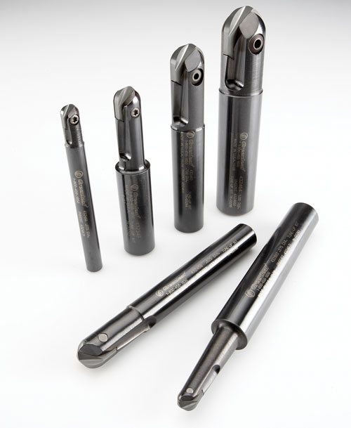
The cutter bodies for the ballnose inserts are manufactured from heat-treated alloy steel and are available in standard and extended lengths. Diameters range from 3/8 to 1.0 inch.