
Between Centers And Centerless Grinding In One Setup
It sounds like a contradiction in terms-between centers and centerless grinding on one machine. But for some categories of workpieces, it's a viable production process that can yield machining time reductions of 45 percent over separate grinding operations.


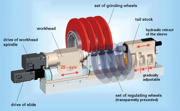
Shown is the schematic structure of the Kronos L dual. Callouts illustrate the operational details of the setup for a typical camshaft.
Efficient production of workpieces with concentric features is streamlined using between center grinding and centerless grinding in one setup.
It sounds like a contradiction in terms—between centers and centerless grinding on one machine. But for some categories of workpieces, it's a viable production process that can yield machining time reductions of 45 percent over separate grinding operations.
In general, OD grinding is performed either between centers or on a centerless grinding machine. When the features of the workpiece, such as crankshafts, camshafts, armatures or gear shafts require both grinding operations, they are usually done sequentially on purpose-built machine tools.


Primarily a shop uses these grinding operations because of specific strengths inherent in each. For between center work, a workpiece that has a critical concentric feature such as a cam lobe or gear or crank pin is processed between centers because the relative positions to the shaft diameter can be maintained.
Centerless grinding, on the other hand, is best applied for creating roundness. The process is self-correcting for most out of round conditions. It is limited, however, in its ability to maintain concentricity between the shaft diameter and a lobe, gear or pin.
All across metalworking, shops are combining what were once independent production steps into single setup, multi-process operations that can machine a workpiece complete from a blank. In the case of the Kronos L dual from Shaudt, Mikrosa, BWF, two traditionally distinct OD grinding operations are combined on a single machine tool frame. It's basically a centerless grinder that can perform between center OD grinding.
In order to achieve a "2-in-1" process, a workhead and tailstock are installed at either end of the centerless grinder workrest blade. The workhead is equipped with a driver and programmable rotational speed.
Both workhead and tailstock centers are retractable and adjustable to the workpiece length and diameter. A recirculating ball spindle, programmable from the CNC, can position the work spindle axially. On the tailstock side, its center support (MT 4) is arranged with a sleeve that is hydraulically actuated.
In operation, the grinding wheel and regulating wheels are moved back for loading clearance. Once loaded, the shaft is clamped between centers. The wheel head slowly brings the workpiece up to its programmed rotational speed.
Next the grinding wheel is infed to the workpiece. In this operation the regulating wheel is not involved. The workpiece is ground between centers. This step grinds the desired diameters of the workpiece concentric with the centers at a cutting rate from 0.05 mm/min. to 0.10 mm/min. (0.002 ipm to 0.004 ipm).
Following sparkout, the grinding wheel retracts, and the regulating wheel is infed. It forms a prism relative to the workrest blade. With the regulating wheel in position, the work driver and tailstock retract, causing the workpiece to contact the workrest blade.
The Kronos is now in centerless grinding mode. The grinding wheel feeds in, and the workpiece is finish ground using the centerless method. When size is achieved, the wheels retract, the workpiece is unloaded and the process begins again.
For workpieces with features that are concentrically critical yet need the roundness tolerances that centerless grinders provide, this "2-in-1" process can save production time and cost.


Related Content

10 Things to Know About Creep-Feed Grinding
Because of the high material removal rate creep-feed grinding can deliver in challenging materials, grinding might not be just the last step in the process—it might be the process.
Read More
A New Milling 101: Milling Forces and Formulas
The forces involved in the milling process can be quantified, thus allowing mathematical tools to predict and control these forces. Formulas for calculating these forces accurately make it possible to optimize the quality of milling operations.
Read More
Volumetric Accuracy Is Key to Machining James Webb Telescope
To meet the extreme tolerance of the telescope’s beryllium mirrors, the manufacturer had to rely on stable horizontal machining centers with a high degree of consistency volumetric accuracy.
Read More
Inside an Amish-Owned Family Machine Shop
Modern Machine Shop took an exclusive behind-the-scenes tour of an Amish-owned machine shop, where advanced machining technologies work alongside old-world traditions.
Read MoreRead Next


3 Mistakes That Cause CNC Programs to Fail
Despite enhancements to manufacturing technology, there are still issues today that can cause programs to fail. These failures can cause lost time, scrapped parts, damaged machines and even injured operators.
Read More
The Cut Scene: The Finer Details of Large-Format Machining
Small details and features can have an outsized impact on large parts, such as Barbco’s collapsible utility drill head.
Read More