
Boring Bar Adjusts In The Cut
Firms that do a lot of boring of gear boxes, valves, castings and other complex components on horizontal boring mills, floor-type boring mills and similar horizontal-spindle machines should be interested in Controlled Boring Bars and Contouring Heads.


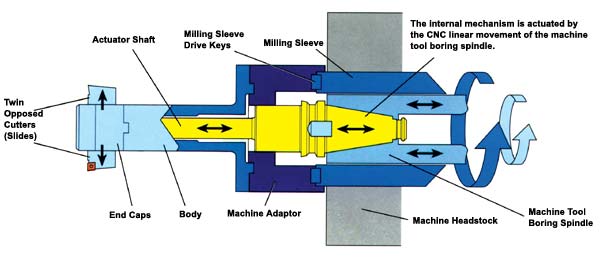
Here's how the Controlled Boring Bar works. The machine tool boring spindle moves laterally under the direction of the CNC while the tool is in the cut. The corresponding linear motion of the actuator shaft is translated 90 degrees, moving the opposed cutters toward or away from the tool body.
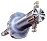
The ITS Controlled Boring Bar's cutters extend and retract during machining, allowing the user to perform a wide variety of operations with a single setup.
Firms that do a lot of boring of gear boxes, valves, castings and other complex components on horizontal boring mills, floor-type boring mills and similar horizontal-spindle machines should be interested in Controlled Boring Bars and Contouring Heads. Designed and manufactured by Innovative Tooling Solutions, a division of the Scottish company Forth Tool & Valve Ltd., this tooling technology is establishing itself within the United States metalcutting industry.
Unlike conventional boring tools, where the cutters are set to machine a desired diameter, ITS Controlled Boring Tools permit changes to be made in the cutting diameter during the actual machining process. (See accompanying illustration.) CNC machine tools equipped with the boring tool not only accommodate multiple diameter changes, but also accommodate the machining of such complex geometries as tapers, radii, chamfers, profiles and threading. A wide variety of machining operations can be performed with a single tooling setup. The tool can be used for forward, back and intermittent boring and for roughing, semi-finishing and precision finishing.


The ability to control the diameter of the cutter(s) dramatically reduces the need for time-consuming changes and secondary operations. This in turn results in significant increases in productivity. The system is so flexible that new product designs or design changes can be accommodated by simply changing the machining program, avoiding the expense and delay of additional tooling purchases.
How It Works
The boring bar has a main body that attaches to and is rotated by the machine tool's milling sleeve. A precision mechanism moves back and forth within the main body, actuated by the linear movement of the machine tool boring spindle. (See diagram.) The linear movement, which is controlled by the machine tool's CNC, is translated 90 degrees, via the actuator shaft, resulting in radial movement of the cutters. According to the manufacturer, the rigidity of the boring bar and the precision of its internal mechanism enable the tool to accurately reflect the contouring capabilities of the machine tool on which it is mounted.
The boring bar is not dedicated to a particular machine. It can be moved from machine to machine within the shop. The only requirements for installing the boring bar on a machine are that (1) the lateral movement of the boring spindle be under CNC control, (2) the machine have an independent co-linear axis—that the machine tool's table or column move in the same direction as the boring spindle, and (3) the boring spindle and milling sleeve rotate in unison.
In addition to the twin-cutter controlled boring bar series shown, the ITS product line includes a single-cutter boring bar series, an extended-reach boring bar series and a micro boring bar series developed for high speed, small-bore applications. The line also includes a series of heavy duty contouring heads designed for internal and external operations.
Related Content
-
How to Turn Machine Shop Downtime Into Process Expertise
To take advantage of a lull in business, JR Machine devised a week-long cutting tool event that elevated the shop’s capabilities with aerospace alloys.
-
New Machining Technology Works With Old to Restore WWII Submarine
A set of donated boring bars that can be used in a 1954 boring head will enable volunteer machinists to recreate a pair of binoculars for the USS Pampanito.
-
Walter Offers New Solid-Carbide Taps for Blind-Hole Machining
Walter’s TC388 Supreme and TC389 Supreme feature patent-pending cutting geometries that fully shear off the root of the chip when reversing, thus minimizing torque peaks.


