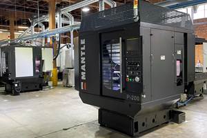
Breaking The Electrode Bottleneck
This company uses high speed machining to slash the time it takes to make graphite electrodes for EDMing of molds and dies. From days to hours. Sounds like a simple, straight-forward formula for cutting costs and lead times, doesn't it?
Pro Mold & Die uses high speed machining to slash the time it takes to make graphite electrodes for EDMing of molds and dies. From days to hours. Sounds like a simple, straight-forward formula for cutting costs and lead times, doesn't it?
Well, it's a lot more complicated than that. Ask Dave Long. He's the production manager and one of the founding partners of Pro Mold & Die, a forward-looking and innovative mold and die shop located in Roselle, Illinois, a suburb of Chicago. He'll tell you that, in many ways, high speed machining is not an evolutionary change but a revolutionary one. Many aspects of the shop are set up differently so it can do high speed machining. It's the corner stone of their mold and die production strategy.
High speed machining has had an especially profound effect on the production of electrodes and that has had a profound effect on how the shop uses EDM to make molds and dies. It's rewritten all of the old rules.
At Pro Mold & Die, high speed machining is the key to significant savings in total electrode production time as well as significant improvements in electrode quality. Together, these benefits lead to significant savings in EDM "burn" time as well as improved EDM results.
Habitual Innovators
Pro Mold & Die was founded in 1973. Dave Long and Walter Schaub were two of the original partners and both are still very much involved in the day-to-day operation of the company. Mr. Long is the hands-on, out-in-the-shop-a-lot Vice President of Production. Mr. Schaub is the deal-with-customers executive, whose title is President of Engineering.
This 45-man shop has a history of adopting technology while that technology is still new. Since 1982, it has had in-house capability for programming CNC (computer numerically controlled) equipment. In 1984, the shop added 3D CAD/CAM in its design and engineering departments. On average, this CAD/CAM capability has been updated every three years or so. The shop has been doing 3D machining since 1984.
About two years ago, Pro Mold & Die began its move into high speed machining of graphite. It upgraded an existing machine with a new control, only to find then that the original spindle was totally inadequate. An electric spindle with top speeds of 25,000 rpm replaced the old one. Now this machine routinely runs at 150 to 300 ipm, whereas 20 ipm had been the norm before the upgrade.
More recently, the shop purchased a new machining center specifically designed for graphite milling. A larger and more powerful machine, this vertical mill has a 12,000-rpm spindle and accepts end mills up to 1 inch in diameter. Feed rates of 400 ipm are possible but 150 to 300 ipm are typical on complex geometry. Although these two machines represent the shop's facilities for high speed machining of graphite, a half-dozen other CNC machines are also set up for high speed machining of steel mold cavities, cores and components.
In the EDM area, the shop has five ram EDMs, three of them CNC. All of these machine are busy, especially with a streamlined process in place for generating electrodes.
A Better Way To Make Better Electrodes
As an electrode production technique, the essence of high speed machining is making a lot of finishing passes at very small stepovers at very high feed rates. It is not necessarily faster, in terms of total milling time, notes Mr. Long. "The machine tool may be moving the cutter ten times faster than a conventional machine would, but it is making five times as many cuts," he explains.
Sometimes high speed machining does mean completing an electrode, usually one with relatively simple geometry, in less time, and that can be a critical advantage. But the most significant time savings lie else-where, most notably in reducing or eliminating benchwork and polishing. Typically, the time reduction is in the neighborhood of 50 to 75 percent.
More important, eliminating most hand work means that the as-machined geometry will not be lost. "Once you get to the bench, you run the risk of deviating from the geometry in the customer's CAD file. You don't really know what you've got," Mr. Long explains.
High speed machining allows the shop to produce electrodes that are virtually identical to the customer's actual geometry. By vastly increasing feed rates during finish machining, the stepover from pass to pass of the cutter can be greatly reduced without adding excessive machine time.
In a typical case, stepovers may be as little as 0.001 inch, leaving cusps only 0.00005 inch high. In many cases, the surface quality is so fine that little or no benchwork is required. Where benching is required, it usually can be accomplished without power tools because far less material needs to be removed. For example, hand polishing may begin with 320-grit stones, instead of coarser 80- or 100-grit stones.
If more than one electrode must be produced, each "copy" will be exactly alike when benchwork can be reduced or eliminated. No two individuals can grind or polish exactly the same way, and even the same individual cannot obtain exactly the same results twice, whereas a computer-controlled machine produces the same results each time. Having electrodes that are virtually the same means that virtually identical cavities can be formed at the EDM. This is a plus for multicavity molds for producing interchangeable, injected plastic parts, Mr. Long points out.
Highly consistent, as-machined results also mean that EDM time can be reduced. For example, the shop routinely machines a roughing electrode that is 0.015 to 0.020 inch undersize and another electrode that is 0.005 to 0.010 inch undersize as a finishing electrode. (The undersizing allows for the spark gap, or overburn, that is inevitably involved in ram EDM.) If the difference between the roughing and finishing electrodes is not uniform on all surfaces (especially at corners), the uneven stock conditions cause the finishing electrode to burn much more slowly.
High spots or oversized corner radii will begin sparking first, and because these represent a very small surface area, metal removal rates will be very poor. A near perfect match between electrodes, however, will create optimum conditions for efficient EDMing when the finishing electrode is introduced.
So high speed machining offers a triple bonus -- it drastically reduces or eliminates the time-consuming step of hand polishing, which means that the electrode geometry will be more accurate and more consistent, and that in turn means faster and more highly repeatable EDMing. But that's not all.
Thin Ribs For Deep, Narrow Slots
Another advantage of high speed machining comes out when producing electrodes with thin walls or ribs. Graphite is a very brittle material. With high speed machining, stepovers as fine as 0.001 or 0.002 inch put very little pressure between the cutter and the graphite, whereas conventional machining would almost always cause the rib or wall to break off before being completed.
Being able to machine thin walls and ribs allows one-piece electrodes with all ribs in place to be produced. The mold for a telephone handset is a perfect example of how useful this thin-rib machining can be. The cavities for this mold were produced with three electrodes. Formerly, each rib would have to be machined separately and EDMed separately, multiplying the machining and EDMing time many times over, not to mention all the time that was required to replicate setups and locate the electrodes with numerous indicator readings.
All that time was saved with one-piece electrodes. Eliminating the multiple setups also eliminated the location errors that may have occurred and accumulated between setups. "It's a nightmare averted," remarks Mr. Long.
Electrodes In A Hurry
There are situations, however, where simply being able to generate an electrode quickly makes a major difference. This is a basic benefit of high speed machining not to be overlooked.
"It's not unusual for us to have a roughing electrode on the EDM sinking a cavity while we are still machining the finishing electrode on the machining center," Mr. Long reports. "We know the second electrode will be finished before the first one is off the EDM, with no idle time in between. We used to wait until all electrodes were completed before moving to the EDM, but that delay is unnecessary now."
And if a customer calls in last-minute design changes, the shop is able to accommodate them, knowing that machining a new or modified electrode will not seriously disrupt tightly scheduled shop resources.
Rapid electrode production allows another beneficial tradeoff at the EDMs. The shop uses negative polarity on the electrode more frequently. Although reversing the polarity causes much greater electrode wear, it also substantially increases the metal removal rate. The answer to rapid electrode wear is simply to make additional electrodes. The added cost and extra time involved is more than made up for in reduced time on the EDM.
The shop finds this tactic especially useful when sinking deep slots with rib-shaped electrodes. "If three more hours for an extra electrode will save us ten hours on the EDM, this is clearly a favorable tradeoff," Mr. Long says. "Reversing polarity like this is another bullet in our gun."
An Infrastructure
Altogether, the benefits of high speed machining for graphite electrodes are compelling, but what a shop has to "get together" to do it is no trivial matter. It's a lot more than machine tools that can machine at high speed. A shop also needs the infrastructure to support high speed machining. Among other things, that "infrastructure" includes the CNC programming capability to generate tool paths and a means of getting the program to the machine tool for execution.
To start, Mr. Long stresses the importance of having strong CAD/CAM capability. CNC programs for high speed machining are very long. With very small stepovers, the cutting tool makes many more passes across the workpiece than in conventional machining. If the surface being generated is a complex one (and that is often the case in mold and die work), the tool path for even a single pass may involve a great number of machine commands. Without a powerful CAD/CAM system to handle the extensive processing required to generate such long programs, CNC programming would become a serious bottleneck, negating many of the benefits derived from high speed machining.
Pro Mold & Die is currently using the latest version of CADDS5X software from Computervision (Bedford, Massachusetts) running on Sun Sparcstation hardware platforms to do tool path generation for high speed machining. (The shop has a variety of other software and hardware combinations for doing design, engineering and NC programming of mold bases and other utility machining applications.)
According to Don Donnelly, Pro Mold & Die's systems manager, and Tim Fritz, manager of CNC programming, high speed machining demands a system with very strong surfacing capability, in other words, the power to define complex geometric shapes represented by a continuous "skin" on the outside of the object. A very accurate and complete surface must be defined because tool paths will be constructed over this surface to reproduce the corresponding shape on the workpiece.
The company routinely works with part geometry received as solid models downloaded by modem from the customer. Pro Mold & Die has four IGES translators available and usually uses at least two of them to get an adequately complete translation. Tool paths most often are created directly from the geometry, usually there is no need to generate dimensioned drawings or prints and none are used on the shop floor.
To show how important processing speed of the CAD/CAM system is to high speed machining, Mr. Fritz points to a mold for an automotive hub cap the shop has produced. Originally, processing time to generate the tool paths for 0.025-inch stepovers took a little over 22 hours just a few years ago. With subsequent upgrades to their CAD/CAM system, processing time for the same tool paths dropped to about two hours, then 20 minutes, and today it can be generated in about 12 minutes.
Processing speed for CNC programming is also the key to streamlining the production of multiple electrodes sized differently for roughing and finishing, because each one requires its own set of tool paths. Such an approach would lose much of its appeal if excessive processing time stood in the way. Reprocessing a CNC program is likewise a non-issue. If the shop floor experiences chatter in a cut, for example, programmers can make adjustments to the original machining parameters and release the revised program with only minimal impact on the shop schedule.
Another benefit is the ability to generate a CNC program to redress an electrode for additional "burns" on the EDM. "This is one of the savings that we hadn't anticipated in our high speed machining strategy," says Mr. Long. "In some cases, we redress the roughing electrode to use as an additional finishing electrode." The savings in graphite costs alone make this a plus, he says. For larger electrodes, this may represent several thousands of dollars. It works because the used electrode can be measured for wear and a new program to compensate for those values can be processed immediately, in time to do the machining before the electrode is needed at the EDM again.
Moving Long CNC Programs Around
Another "infrastructure" issue raised by high speed machining is dealing with those exceedingly long CNC programs and getting them to the machine tool for execution. Executing multi-axis moves quickly entails processing machine commands in the CNC at a high rate which means data has to flow to the CNC unit at a high rate as well. When it doesn't, "data starvation" is the result and the cutter may hesitate as it waits for the CNC to catch up, leaving unacceptable dwell marks marring the electrode surface.
Pro Mold & Die's way around this difficulty is a shop-wide Ethernet network that connects all computer workstations, peripheral devices such as printers or plotters and the CNCs. This network gives the shop several options for handling massive CNC programs.
At The Machines
At Pro Mold & Die, the two machines used for graphite milling make an interesting contrast. The differences and similarities reflect some of the subtle nuances in technology that make high speed machining the dynamic development it is.
The one machine is a vertical machining center (VMC) from Kitamura (Wheeling, Illinois) that the shop retrofit for high speed graphite milling in 1995. Originally, the conversion consisted of adding a vacuum system to control dust and retrofitting a new CNC from Creative Technology Corporation (Arlington Heights, Illinois). This PC-based CNC features open architecture and 1,000-block look-ahead capability. This machine is capable of feed rates of 350 ipm.
What the shop learned right away, however, was that the original spindle was no longer adequate. High feed rates require high spindle speeds to keep chip loads high enough for efficient material removal and predictable tool life. Shortly after the CNC retrofit, the shop had a spindle installed for rpm up to 25,000. This spindle, an electric model, is cooled with refrigerant lines to control thermal growth.
Another lesson this machine confirmed is that look-ahead features of the CNC are essential to high speed machining of 3D contours. "Look-ahead" is the ability of software embedded in the CNC processor to evaluate changes in axis motion and respond before it is too late for the machine to adjust in time. This allows the machine to maintain high feed rates but avoid gouging surfaces or rounding corners by automatically adjusting feed rates. Without the optimizing effect that look-ahead provides, Mr. Long believes that high speed machining would be far less worthwhile because accurate machining of contours would not be feasible. This is especially true when milling graphite because the extremely machinable nature of this material is conducive to using a machine's maximum feed rates.
Another crucial feature of the CNC on this machine is the built-in network architecture that allows it to connect directly to the shop's Ethernet network hub. This Ethernet connection replaces a conventional DNC interface and allows program data to feed at rates ten times faster than typical DNC baud rates permit. Three other machines at Pro Mold & Die have been retrofit with CNCs from Creative Technology and all are interfaced directly to the network in this manner.
More recently, the shop installed a TRC 500 VMC from OKK (Glendale Heights, Illinois) that is especially designed for graphite milling. This machine was equipped by the factory with a 12,000-rpm, 7-hp spindle that accommodates a 1-inch end mill (the other machine is limited to 1/2-inch end mills). The machine enclosure incorporates a highly efficient dust removal system.
Unlike the first graphite machine, this VMC has a Fanuc CNC with a 256-MB hard drive, giving it enough internal computer memory to store the very long CNC programs encountered in high speed machining. And like the other graphite mill, the look-ahead feature on the Fanuc CNC is substantial, it looks ahead 120 blocks. What distinguishes the OKK machine is its mechanical construction. With linear ways on ball bearings and a traveling head, it is more responsive to axis moves, having less mass to maneuver. So even though the top feed rate (400 ipm) and top spindle rpm of this machine do not match that of the slightly smaller Kitamura, the OKK takes corners faster and has quicker axis acceleration and deceleration rates, rendering its overall performance very comparable.
"Even so," remarks Mr. Long, "these machines have different personalities. Larger electrodes are generally better suited to the OKK but if there are smaller, more complex details, the Kitamura is likely to be the choice." Mr. Long says that the shop needs both machines to cover the range of electrodes and the volume of graphite his shop machines. "We couldn't get along with just one or the other."
A word about cutting tools: For machining graphite at high speed, single-flute, brazed diamond insert cutters are clearly the tools of choice in this shop. Diamond cutting edges show virtually no wear in graphite, which means better surface finishes (a real consideration if polishing is to be avoided). Diamond tools are precision ground and the shop finds that they usually have greater dimensional accuracy than their solid carbide counterparts (also a real consideration when tightly toleranced electrode surfaces are being generated).
In Another Context
Although high speed machining has given Pro Mold & Die many strategic advantages, it would be a mistake to think that the shop's success is based solely on its technical capabilities. The skill and experience of its workforce and the savvy leadership of its top managers make a big difference.
In this context, open architecture, communication networks and processing power have another meaning. Open architecture, for instance. Pro Mold & Die's new building features a spacious conference room situated between the front office and the design/engineering wing but with picture windows looking out into the shop area. This is where project managers assemble the entire mold design and production team each week to plan mold-building strategies and review completed jobs to share ideas and suggest improvements. That kind of communication network is every bit as important as anything Ethernet provides. And when creative minds come together to solve problems and work out challenging job situations, this is the processing power that is the competitive edge the company depends on.
Finally, Pro Mold & Die's production staff benefits from the hands-on involvement of its top managers. Dave Long and Walter Schaub are leaders who recognize that they have to stay in touch but they don't have to be in control. Project managers and their teams have a lot of responsibility but a lot of leeway, too.
High speed machining has helped this shop break the electrode bottleneck, but more important, this shop knows how to make the most of every break it gets.
Related Content
Tool and Die Shop Discovers New Opportunities With First CNC Machine
In a shop that stamps millions of parts per year, the arrival of a CNC machining center is opening new pathways for production and business.
Read MoreCimatron's Updated CAD/CAM Software Streamlines Mold Design
Eastec 2023: Cimatron V16 includes a clean new user interface and increased automation for faster mold design, electrode creation and NC programming.
Read MoreTwin Spindle Design Doubles Production of Small Parts
After experiencing process stalls in the finishing stage of production, Bryan Machine Service designed an air-powered twin spindle and indexable rotating base to effectively double its production of small parts.
Read MoreIn Moldmaking, Mantle Process Addresses Lead Time and Talent Pool
A new process delivered through what looks like a standard machining center promises to streamline machining of injection mold cores and cavities and even answer the declining availability of toolmakers.
Read MoreRead Next
The Cut Scene: The Finer Details of Large-Format Machining
Small details and features can have an outsized impact on large parts, such as Barbco’s collapsible utility drill head.
Read More3 Mistakes That Cause CNC Programs to Fail
Despite enhancements to manufacturing technology, there are still issues today that can cause programs to fail. These failures can cause lost time, scrapped parts, damaged machines and even injured operators.
Read More







.png;maxWidth=300;quality=90)
