
Diaphragm Chucks Break A Bottleneck
Finding a better way to hold the part meant more parts per shift, better tool life and improve surface finish.


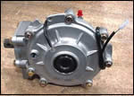
A finished part is ready for unloading from the right spindle. The inset shows the completed differential assembly.
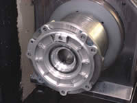
A finished part is ready for unloading from the right spindle. The inset shows the completed differential assembly.
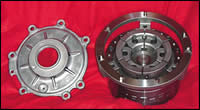
The cover plate at left shows the raised boss that provided the only OD surface for chucking the part. Next to it is the diaphragm chuck customized for holding this part. Note the drive pins on the outer locator ring that serve to orient the part.
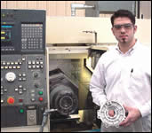
J.C. Holleran holds one of the cover plates next to the twin spindle lathe on which the part is turned in two chuckings.
A lathe chuck should hold your part, not hold you back.
J. C. Holleran, a manufacturing engineer at The Hilliard Corporation in Elmira, New York, was confronted with a situation in which conventional three-jaw chucks were holding him back. His company was machining a dish-shaped part on a twin-spindle turning center.


The three-jaw chucks were already having some problems with this part, and orders for the part were going up. Mr. Holleran needed to solve the problems with the chucks and find a safe way to increase the output of the turning center. The alternatives were adding substantial overtime or purchasing a second machine. Neither of these choices was attractive given the pressure on costs that he, like everyone else in manufacturing, was facing.
Replacing the original chucks with diaphragm chucks solved the difficulty. Instead of sliding jaws, these chucks use a flexible steel membrane that acts as a powerful spring to create the clamping force.
Not Much To Grip On
There was nothing wrong with the original chucks on the twin-spindle machine, an Okuma LFS15, Mr. Holleran explains. It was the odd shape of the workpiece that was creating the difficulty. "There's not much to grip on," he says.
The part is a cast aluminum cover plate for a differential housing. It is about 8 inches in diameter with a 2-inch center bore. A raised boss surrounding the center bore on the backside of the part provided the only surface for chucking the part, as shown in the photo on page 93. The jaws of the original OEM chucks gripped the OD of this boss. "We had about a quarter inch of length on the boss for the jaws to hold on to," Mr. Holleran says.
The cover plate is an important part of a front differential for a four-wheel drive all-terrain vehicle. Hilliard Corp., a major North American supplier of clutches, manufactures the differential assembly for Polaris Industries, a leading maker of ATVs, snowmobiles and other recreational vehicles. This Hilliard bi-directional centralized front end differential is installed on almost all of Polaris' four-wheel drive ATVs. The Hilliard differential allows the rider to shift to four-wheel drive as needed, by engaging a clutch inside the front differential. This "4WD On Demand" feature is a key selling point for the Polaris ATV line. Hilliard began producing the differential in early 2001, when it installed the twin-spindle turning center for machining the cover plate.
The part is machined in two setups. The raw casting is first chucked in the left spindle for roughing all bores and faces. A face groove is also roughed and finished in this setup. The part is then unloaded and moved to a pneumatic press next to the lathe, where a cup-shaped coil pocket insert of cold rolled steel is press fit in the finished face groove.
The part then returns to the right spindle of the lathe and is rechucked on the center boss as before. All bores and faces are then finish turned.
The Parts Aren't Frisbees
Although the lathe spindles are rated at a top speed of 4,500 rpm, the three-jaw chucks were limited to 3,000 rpm. At higher speeds, centrifugal force could cause the jaws to spread and lose their grip on the workpiece. Even at 3,000 rpm, these chucks were not entirely reliable, Mr. Holleran reports.
"Once or twice a week, a part would leave the chuck. When this happened, it would take us about 8 hours to get back into production," he says. After each incident, the jaws had to be reworked. Sometimes damage to a cutting tool also occurred, creating additional delays.
The chucks also presented some maintenance issues. The jaws were made of aluminum to reduce mass and lessen the effects of centrifugal force. However, the aluminum jaws wore more quickly, requiring replacement about once a quarter.
The lower spindle speed imposed by the chucks also affected tool wear and surface finish. On the smaller bores, the limited rpm was inadequate to achieve the best cutting conditions. The carbide inserts on these tools had to be changed once a shift or more often.
Because of the restrictions on machining speeds and the considerable amount of downtime, the twin-spindle turning center was able to produce about 220 parts per shift. This quantity was barely adequate to keep up with customer demand. However, about a year ago, order quantities increased and, according to Mr. Holleran, this machining operation became a serious bottleneck.
A Different Kind Of Chuck
John Gulyas, one of the CNC programmers at Hilliard, suggested to Mr. Holleran that diaphragm chucks be considered for this application. The programmer had worked with this kind of chuck while working at another company. The diaphragm chucks there had been manufactured by Northfield Precision Instrument Corp.(Island Park, New York). These chucks do not use sliding jaws to clamp a workpiece. Instead, a segmented ring collapses around an OD, making contact on almost the entire diameter of the part.
Mr. Holleran could see the inherent advantage of this kind of chuck. Increasing contact with the shallow boss on the cover plate would create more clamping force, allowing spindle speeds to go up.
Mr. Holleran sent prints of the cover plate to Paul DeFeo, chief engineer at Northfield. He recommended that the three-jaw chucks on both spindles be replaced with customized 7-inch diaphragm chucks. Although the diaphragm chucks cost about twice the price of comparable sliding jaw chucks, the expected benefits of the new chucks made them easy to justify to Mr. Holleran's managers.
The new chucks were installed in June 2003. Unlike the three-jaw chucks they replaced, the diaphragm chucks are pneumatically, rather than hydraulically, operated. Hilliard's maintenance crew did the installation over the period of three shifts. Disconnecting the unneeded hydraulic lines on the lathe represented the major chore in this procedure.
The new chucks are rated at a maximum speed of 8,000 rpm, well above the 4,500-rpm top speed for the lathe.
The chucks are customized in several important ways. Each chuck is fitted with a locator ring for positioning the cover plates. Ground dowel pins on the locator rings match the bolt holes on the cover plate. These pins not only orient the cover plate but also act as drivers for the part. The jaws are milled so that they fit inside the support ribs that are features of the casting. The locating pins orient the part properly to provide the necessary clearance.
To maximize the gripping power of the steel jaws, the contact surfaces are hardened and ground and have a coating of diamond grit. The grit bites into the casting, greatly increasing the coefficient of friction. According to Mr. Holleran, the new chucks have not lost a single workpiece since installation.
The diaphragm that gives this kind of chuck its name is a flexible saucer-shaped steel plate normally bowed slightly to create a powerful spring action closing the jaws. An air-operated actuator pushes the steel plate from the rear and relieves the spring force slightly, opening the jaws enough to load and unload the workpiece. "It's a bit like the bottom of an old-fashioned oilcan," Mr. Holleran explains.
The action of the diaphragm does not involve any metal-to-metal moving parts, so there is no wear. No lubrication is required.
Whereas a sliding jaw chuck has a tendency to lift the workpiece away from the chuck face as it grips, a diaphragm chuck pulls the workpiece inward. In this case, the flange on the cover plate is pulled against the ground face of the locator ring. The inward force of the chuck also makes chucking the part more rigid and secure. The jaws of the chuck have less mass than those on a sliding jaw chuck, reducing centrifugal force.
A Cascade Of Benefits
Because the new chucks allow the lathe to turn at its top rpm, Mr. Holleran could switch to polycrystalline diamond (PCD) inserts for the finish boring, turning and facing operations. PCD had been tried with the original chucks to improve tool life and reduce downtime for changing inserts, but the rpm attainable was insufficient for the PCD to perform well.
The new chucks allow spindle speeds that approach the optimum surface speeds for PCD. According to Mr. Holleran, the PCD inserts typically last three to six shifts per edge compared to one shift or less with the carbide inserts. The PCD tooling also produces better surface finishes, a function of turning at higher spindle speeds. "We are required to hold a 24 Ra finish on one of the faces of the part," Mr. Holleran says.
The biggest advantage of the new chucks comes from eliminating the downtime associated with jaws damaged by thrown parts. Other savings also appeared. Because the jaws of the diaphragm chucks are hardened steel, they are long-wearing and do not require periodic reworking. The new chucks do not require daily lubrication or other maintenance.
With the new chucks in place, the output of the turning center has increased to 250 parts per shift. This increase in productivity allows the machine to keep pace with current part demand.
According to Mr. Holleran, the company is looking at applications in other product lines that might benefit from an upgrade to diaphragm chucks. "We wouldn't hesitate to make the switch in applications where we discovered that conventional chucks were still holding us back," he says. Diaphragm chucks will also be considered for future applications.


Related Content

Modern Bar Feeds Bring New Life to Automatic Swiss Lathes
Cam-actuated Swiss lathes are still the fastest way to process many parts. By adding modern bar feeders, this shop has dramatically improved their utilization with the ability to work unattended, even in a lights-out environment.
Read More
Quick-Change Tool Heads Reduce Setup on Swiss-Type Turning Centers
This new quick-change tooling system enables shops to get more production from their Swiss turning centers through reduced tool setup time and matches the performance of a solid tool.
Read More
Romi Launches Flatbed Lathe for Machining Large Parts
The C 1100H is a heavy-duty flatbed lathe built with a monoblock cast iron bed that absorbs machining efforts and vibration, making it highly rigid, stable and accurate.
Read More
Digital Twins Give CNC Machining a Head Start
Model-based manufacturing and the digital thread enable Sikorsky to reduce lead times by machining helicopter components before designs are finalized.
Read MoreRead Next

Aligning Critical Bores
A chuck/fixture combo enables a gage maker to drill perfectly aligned holes in dial indicator housings.
Read More

3 Mistakes That Cause CNC Programs to Fail
Despite enhancements to manufacturing technology, there are still issues today that can cause programs to fail. These failures can cause lost time, scrapped parts, damaged machines and even injured operators.
Read More