
Company Increases Manufacturing Capability With CAM System
This manufacturer is a 'one stop shop' offering custom machining and manufacturing, precision sheet metal work and prototyping, as well as long and short production runs.


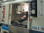
W.C. Machine & Tool has automated programming on its CNC machine tools such as this one with the ESPRIT CAM system, which uses feature recognition capabilities to simplify the programming of the company's electronics enclosures.
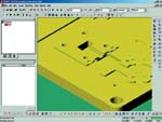
ESPRIT allows W.C. Machine Tool to create tool paths for its complex parts in an hour because the programmer no longer has to spend time manually selecting features.
W.C. Machine & Tool Inc. (Chandler, Arizona) is a "one stop shop" offering custom machining and manufacturing, precision sheet metal work and prototyping, as well as long and short production runs. Its end-to-end services include CAD/CAM design, CNC and EDM machining, heat treating, sheet metal work, grinding, welding, inspection and more. Having all these disciplines in-house gives the company complete control of projects. Its two-shift operation provides 3,000 hours of shop capacity per month. The company's ability to respond quickly when fast turnaround is required has brought in a great deal of business, allowing the company to grow from five employees to 35 in the last few years.
As the company acquired its CNC machines, it also purchased a CAM system to automate the programming of these machines. This system saved time, but only on simple parts. The programmer selected a start point; indicated the direction of travel; specified tools, feeds and speeds; and gave the command to create the tool path. However, complex parts still required a great deal of manual effort to program with the old CAM system. In these parts, geometric features such as bosses, grooves and holes also had to be selected manually. Then the programmer had to manually enter machining parameters, such as cutting depth, for each individual feature. Although default parameters were presented, even when they were appropriate, it was still very time consuming to have to go through a complex part and identify every feature.


Some of the electronics enclosures that the company makes are particularly time-consuming in this regard. The enclosures consist of multiple pieces. On the outside, they are solid planes. The inside surface, however, is very complex with numerous pockets and islands that printed circuit boards fit into. The geometry is complicated by the fact that the pockets surrounding the islands are different depths. In the past, these parts could take 4 to 8 hours to program manually because each pocket had to be selected individually and then assigned the correct cutting depth.
Then the company purchased a new CAM system, ESPRIT, from DP Technology. The CAM system's Automatic Feature Recognition (AFR) eliminated the need to manually select individual features such as pockets, islands, holes, bosses and grooves. AFR identifies them directly from the imported solid, surface or wireframe models. It also recognizes properties and relationships of part features. "We now select all the features on those complex electronics enclosures with just three mouse clicks," says Chris Albrecht, programmer at W.C. Machine & Tool. "What used to take up to 8 hours is now done in seconds." His increased productivity has allowed the company to increase sales and profits significantly. "With these tasks now being performed automatically by the CAM system, I can program eight times as many parts per day as I could in the past," says Mr. Albrecht.
With ESPRIT, CNC programming for those electronics enclosures now begins with the import of the customer's CAD file in STEP format. Mr. Albrecht uses AFR to highlight all pockets and other features that need to be cut. Then he invokes another automated programming capability: a pocket machining cycle that automatically creates the tool path to cut the pocket using the "Feature" information. This automated pocket machining cycle handles unlimited complexity in both pocket profiles and number of islands. Other automated machining cycles are also available. For example, when a workpiece requires contour cutting of a profile, all cutting depths, cutter compensation and draft angles are calculated automatically.
Once features have been automatically identified and pocket depths have been calculated, the programmer specifies the tools to be used. Tools can be chosen from a tool library or created specifically for each job. Mr. Albrecht usually creates them for the particular job because it gives him more control over the machining process. Then he defines feeds and speeds. On the electronics enclosures, he mainly uses the default feeds and speeds that have been set up in the CAM system for all the different materials. At times, he will adjust the speeds to suit the tool, such as when he wants a smaller or larger end mill than is normally used. "Otherwise, ESPRIT automatically makes these selections, and it works very well," says Mr. Albrecht.
The next step in the process is generating the tool paths. This step is done through a single command window. In the window, Mr. Albrecht enters clearance values and then gives the command to create the tool paths. Before giving the command to generate the G code, he views a simulation of the tool paths on the screen. "The simulation shows the removal of material from a solid model," Mr. Albrecht explains. "I look at it to make sure it's cutting just what I want."
W.C. Machine & Tool has grown quickly in the last few years and has kept up with a large increase in work volume, in part because it can offer fast turn around. Automated NC programming capabilities are making it possible for W.C. Machine & Tool to create tool paths for complex electronics enclosures in only 1 hour. Because the programmer no longer spends time manually selecting features and specifying machining parameters, his productivity has increased by a factor of eight. Another asset that wins and keeps the business for W.C. Machine & Tool is its very competitive pricing. Here, too, the CAM system plays a role. "Because we can program fast and don't need to hire additional programmers to do the jobs, we can charge less," says Mr. Albrecht.


Related Content

TTI Brings Specialty Gear Production In-House with Multiaxis Machining
By investing in a 3+2-axis machine and utilizing simulation software for diagnostic checks, Techtronic Industries turned a four- to ten-week lead time into a one- to two-week lead time.
Read More
Automated CAM Programming – Is Your Software Really Delivering?
A look at the latest automation tools in Autodesk Fusion 360 software and how forward-thinking machine shops and manufacturing departments are using them to slash delivery times and win more business.
Read More
Building A Powerful Bridge from the CAM Programmer to the Shop Floor Operator
SolidCAM for Operators provides a powerful bridge from CAM programming to the shop floor to best streamline the machine shop process with its CAM part simulation. It provides a clear picture to the operator for setup and prove-out, enables minor G-Code changes and avoids crashes, broken tools and scrapped parts.
Read More
Integrated CAD/CAM Promotes Process Efficiency, Traceability
High-requirement markets are not only searching for good parts — they're searching for proof of good parts. CAD/CAM software can help.
Read MoreRead Next

The Cut Scene: The Finer Details of Large-Format Machining
Small details and features can have an outsized impact on large parts, such as Barbco’s collapsible utility drill head.
Read More

3 Mistakes That Cause CNC Programs to Fail
Despite enhancements to manufacturing technology, there are still issues today that can cause programs to fail. These failures can cause lost time, scrapped parts, damaged machines and even injured operators.
Read More