
Composites Machining for the F-35
Lockheed Martin’s precision machining of composite skin sections for the F-35 provides part of the reason why this plane saves money for U.S. taxpayers. That machining makes the plane compelling in ways that have led other countries to take up some of the cost. Here is a look at a high-value, highly engineered machining process for the Joint Strike Fighter aircraft.
.jpg;width=70;height=70;mode=crop;format=webp)
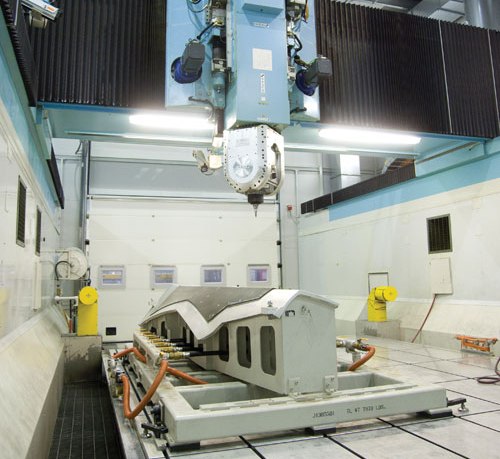
The tight-tolerance FOG machine performs precision milling and drilling of F-35 composite skin sections.
Close-fitting skin sections provide for the F-35's VLO, or "very low observability."
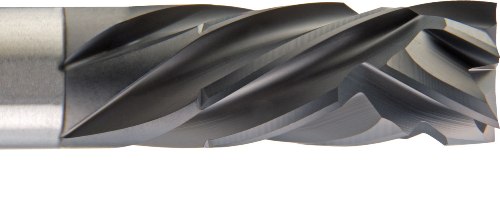
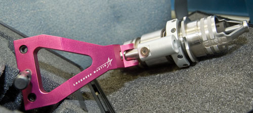
The compression router developed to trim composite skins inhibits delamination by pushing the layers of material together during machining.
Lockheed Martin’s Rick Denny discusses the comression router tool.
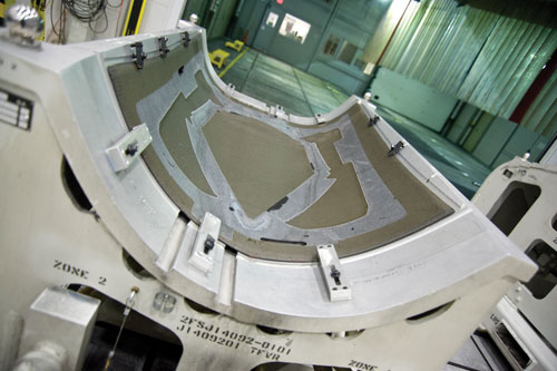
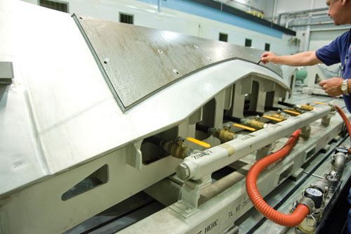
Skin parts are machined in two stages. After the inner mold line (here) is machined, the part will be flipped onto a mirror-image fixture for trimming and outer mold line operations.
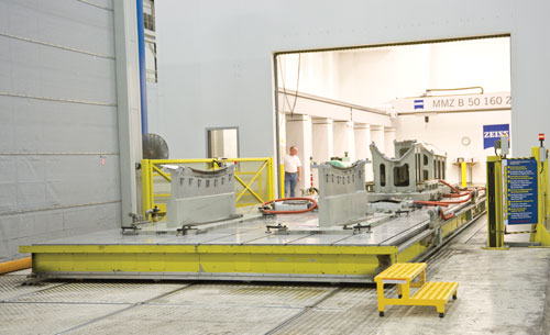
For inspection, pallets move out of the FOG machine to the large CMM seen here.
The PINC tool is one of the more significant cost-saving innovations that have been applied to the process. Developing a means of accurate, automatic countersink placement eliminated the considerable manual involvement that used to go into countersink control.
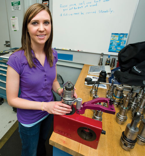
Lockheed Martin’s Jamie Smith was one of the engineers involved in developing the PINC tool.
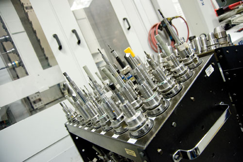
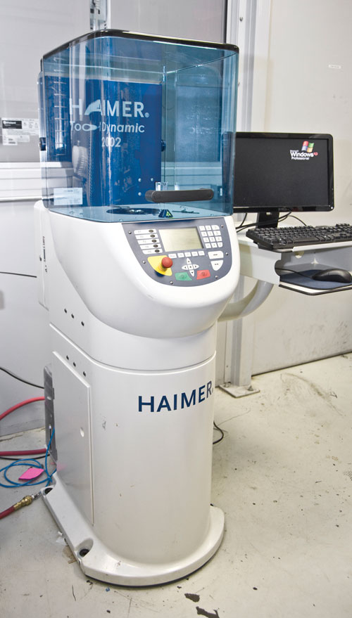
The FOG machine uses hydraulic toolholders measured in a balance machine (next photo).


Different branches of the U.S. armed forces have historically insisted on different aircraft. Air Force, Marines, Navy—they have different missions and face different demands. A one-size-fits-all fighter would obviously be less costly to produce and maintain, but the argument has always been that a fair amount of cost inefficiency is warranted in order to give each branch of the service the equipment best tailored to its role. The result has been a multiplication of military aircraft in which different models fill overlapping uses.
Joel Malone says the multiplication becomes even more elaborate in an age of increased cooperation between international forces. Mr. Malone is a senior manager with the F-35 program at defense aeronautics company Lockheed Martin. He says he saw the effect of this multiplicity on full display during the Bosnia conflict in the 1990s. A coalition airfield held a panorama of different aircraft from the U.S. and other countries. The various planes demanded different supply chains and different maintenance procedures in order to support them all on the battlefield.


Now, technology improvements related to aircraft development and design have made it possible to engineer a single aircraft platform that is adaptable to many needs. The same plane, in different model configurations, can be given short take-off and vertical landing capabilities for the Marines, the resilience needed for carrier landings in the Navy, or the speed and maneuverability prized by the Air Force.
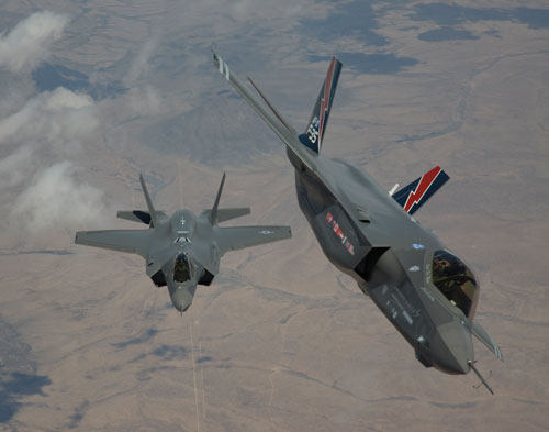
The F-35 Lightning II (also known as the Joint Strike Fighter), produced by Lockheed Martin, is that versatile-use aircraft.
In fact, the possible variations of the plane also make it possible to tailor this aircraft for the U.S.’s various military allies.
However, economics alone were not enough to get the U.S. and allied services to support a common aircraft program, Mr. Malone says. The caution against committing to the same plane as another service, with the design subject to the that service’s needs, was too strong. There had to be a carrot—an enticement making this plane special. On the F-35, that carrot is “VLO,” or very low observability. By radar and other means of sensing, this plane is very difficult to detect.
But the carrot is actually better than that. The F-35 features “supportable” VLO. That is, the VLO on this plane comes with very low maintenance cost.
Stealth aircraft of the past couldn’t make that claim. Because radar detects sharp edges, even small mismatches between exterior parts on past VLO planes were smoothed out using epoxy. The epoxy would dry, harden and separate in the field—meaning it had to be frequently inspected and replaced.
By contrast, adjacent parts of the F-35 match so fluidly and precisely that no epoxy is needed. The trouble with previous stealth aircraft has disappeared.
This benefit—alongside the economics of versatile use—has helped to win the joint support of many military services. They include not just U.S. military branches, but also those of eight other partner countries. Each branch has influence in proportion to its contribution, so the non-U.S. countries have committed more than $4 billion toward the development of the plane. This is money the U.S. taxpayer does not have to spend.
And the payoff is almost directly attributable to CNC machining. Again, per Mr. Malone, supportable VLO is a big reason for the foreign support. What permits the supportable VLO is close matches between parts.
And what permits the close matches? I saw the answer on a recent visit to Lockheed Martin’s manufacturing campus in Fort Worth, Texas.
The answer, of course, is CNC machining. Composite skins are milled and drilled to such close tolerances that the plane’s assembled surface avoids the mismatches that radar can see.
In short, the precision obtained by this company’s CNC machining group has helped to realize a plane that is so effective, and so compelling in its capabilities, that other countries want to help us pay for it.
FOG of War
A sophisticated five-axis milling machine provides this precise milling and drilling of the composite skins. Defense suppliers love acronyms; Lockheed Martin calls this machine the “FOG.” That stands for flexible overhead gantry.
In fact, one of the more interesting items used on the FOG is a device that also goes by an acronym—the PINC. Perhaps unavoidably, the PINC has been colored pink. (More on this device below.)
The FOG was supplied by machine tool maker DS Technology, which has U.S. headquarters in Cincinnati, Ohio. The X-axis pallet length of this five-axis milling machine is 15 meters. Glass scales that provide for positional accuracy and a proprietary DS Technology system for volumetric compensation help maintain tight precision throughout the machine’s large work envelope. Dr. Don Kinard, technical operations deputy for F-35 global production, says he thinks this machine is “the most accurate machine tool in the world for its size.”
Complex contoured parts made of carbon fiber reinforced plastic (CFRP) are machined here, and so are the equally complex aluminum vacuum fixtures that hold the parts during machining. Around 56 composite part numbers are milled, trimmed and drilled in the machine, though that number is likely to decline as part numbers are consolidated for full production. For the typical CFRP part number, the process involves machining the composite part’s IML (inner mold line—or inside surface) while the part is affixed to one vacuum fixture, then machining the remaining features from the OML (outer mold line) after the part has been flipped onto an adjacent, mirror-image vacuum fixture.
During my own visit, the most significant details Lockheed Martin would not disclose were the precise tolerances the F-35 machining process is able to hold. Instead, I learned about the elements of that process.
Here, then, is some of what makes it possible to achieve those unspecified tolerances:
1. Compression Router
Delamination represents the most serious obstacle to accuracy in machining composite parts. This is particularly true when trimming edges. The material is layered, and the force of machining can cause the layers to separate.
Rick Denny is a technical lead for Joint Strike Fighter machining systems. He says a previous cutting tool that was used to trim composites—a tool with PCD edges—would last for only 21 feet. After just this distance, the change in force from tool wear would cause delamination to begin.
The solution was a carbide tool, he says. Specifically, the solution was a “compression router” from cutting tool supplier AMAMCO (American Manufacturing and Marketing Company), developed in partnership with the National Center for Defense Manufacturing and Machining. This tool’s special geometry (see photo) directs cutting forces in a way that compresses the part’s layers together while they are being cut. The tool costs 1/3 the price of the previous tool, he says, but it routinely last for 100 feet before wear becomes a concern.
2. Milling for Thickness
The CFRP parts are precisely built using an automated fiber-placement process, but even that does not control thickness precisely enough. Thickness has to be further controlled through CNC milling. A PCD ballnose end mill machines the inside surface of the part (the IML) in a set of parallel, small-stepover tool paths.
The milling operation takes about 6 hours. Dr. Kinard sees this as one of many aspects of the process that might yet be made more efficient. The machining group is investigating whether the necessary accuracy might instead be obtained using flat-bottom milling tools in a five-axis path that could remove a wider swath of material with each pass.
3. Compensation Even for Concrete
One cause of potential variation is the settling of the shop floor. For stability, the machine sits on a foundation that is 30 feet deep. However, even this foundation is subject to subtle movement over time. To ensure that any settling does not affect machine accuracies, the FOG machine features ceramic gaging spheres that wait in protective housings at the four corners of the machine’s X-Y travels. The machine probes these spheres daily in order to monitor foundation movement.
4. CMM Inspection
For such large workpieces and fixtures, on-machine inspection might seem like the most practical means of verification. That is, just leave the parts in place and measure them at the machine. Dr. Kinard points out the problem with this approach: Even a large CMM would be low-cost when compared to the cost and value of the FOG machine.
Therefore, the more effective use of the FOG is to free it from inspection, even though this means moving the parts. By means of a huge, three-pallet delivery system, each part can be shuttled to a room-sized CMM from Zeiss. To ensure that the vacuum holding the part to the fixtures is not broken during this transfer, a series of independent vacuum tanks travels on each pallet.
5. Special Class of Operator
Understanding the various aspects of this fine-precision process requires special training, and that has led to a new classification of machining technician within the Fort Worth facility. Certain operators at work on the FOG are classified as “STEM,” for special technology equipped machine.
6. Toolholder Attention
Of course, the toolholder is also a vital element affecting process accuracy. Any shop attaining tight machining center precision can appreciate this. Inadequate concentricity, clamping or stability of the toolholding can undermine the rest of the process.
The FOG uses hydraulic holders, with each tool-and-toolholder assembly balanced using a tool-balance measuring machine from Haimer. For long-reach toolholding (a frequent requirement, given the accessibility challenges of the more contoured parts), the process uses Tribos extensions within the hydraulic tooling. “Tribos” is a system from Schunk that uses elastic deformation of the toolholder’s metal as an alternative to heat-activated shrink fit.
7. Countersink Control
Machining countersinks used to be one of the more costly challenges of the process. Because of the precision that even countersinks require on the F-35 skin parts, technicians used to measure holes with manual countersink gages and update machine offsets manually. The procedure was time-consuming and error-prone. Now, the manual work has been eliminated using a device Lockheed Martin developed internally. The device is the PINC, for pressure induced normal-vectored countersink.
Technical fellow Rick Luepke and applications engineer Jamie Smith (pictured) led the development of this tool. The tool, which mounts in the spindle of the FOG, contains the cutting tool (a combination drill/countersink tool) and features a precision-adjustable nose piece that makes contact with the part surface before the cutter does. Through purely mechanical means involving the nosepiece and integral linear compensation, the device lets the machine index off of the part surface so it can place countersinks accurately and automatically. Because it requires no electronic feedback to the machine, it can be used on existing machines without retrofit.
The device is available commercially, says Ms. Smith. Lockheed Martin licensed it for sale by the Jay Enn Corporation of Troy, Michigan. Lockheed Martin’s own version of the PINC is itself partly pink (see photo), but the license agreement specifies no color.
The Second Machine
Seriously, though: The impact of the PINC on the cost of F-35 machining has been pronounced, says Dr. Kinard. The device illustrates just how far a seemingly narrow manufacturing improvement can reach. Automatic countersink machining has translated to greater machine availability because the machine no longer waits for manual hole measurement and no longer loses time to errors in countersink placement. Thanks to these savings, each part costs less to produce, and the Fort Worth facility can potentially meet its needs with fewer FOG machines.
One more FOG is coming, he says. The pit for the next 30-foot-deep foundation has been dug. With the eventual help of still other time-saving and capacity-saving innovations along the lines of the countersink system, the company is hopeful that just these two machines will be sufficient to provide for all of the composites gantry machining demand of the full-production F-35.
Can You Solve This Drilling Challenge?
 This part (pictured to the left) in Lockheed Martin’s assembly area illustrates the number of holes some of the plane’s components routinely need.
How can precision machining be made less expensive? That question—in one form or another—occupies much of the attention of various Lockheed Martin engineers. If the same kind of precision five-axis milling used in the F-35 skin parts could be applied cost-effectively throughout the plane, the result would be higher-performance aircraft that are far less expensive to assemble. The company looks forward to the day when machine-tool technology advances this far.
Meanwhile, Dr. Don Kinard, Lockheed Martin's technical operations deputy for F-35 global production, describes a different manufacturing solution that might have similarly sweeping impact, if only it can be found. In assembly, he says, parts undergo extensive drilling. The photo shows how many holes might be involved in just one component. Some work is done on CNC drilling machines and some is done with engineered hand tools. In either case, many or most of the drilled holes have to be inspected.
But what if there were a way to drill the hole and inspect it at once, all in one pass?
Specifically, says Dr. Kinard, might hole diameter and countersink depth both be confirmed as part of the very same pass that produces these features?
He does not know how such a system would work. Perhaps by using an electrical field for sensing? Whatever the mechanism, finding the solution to this challenge would reduce the cost of hole making on planes that have thousands of critical holes apiece.


Related Content

In Moldmaking, Mantle Process Addresses Lead Time and Talent Pool
A new process delivered through what looks like a standard machining center promises to streamline machining of injection mold cores and cavities and even answer the declining availability of toolmakers.
Read More
Lean Approach to Automated Machine Tending Delivers Quicker Paths to Success
Almost any shop can automate at least some of its production, even in low-volume, high-mix applications. The key to getting started is finding the simplest solutions that fit your requirements. It helps to work with an automation partner that understands your needs.
Read More
Watchmaking: A Machinist’s View
Old-world craftsmanship combines with precision machining on a vertical machining center and Swiss-type lathe to produce some of the only U.S.-made mechanical wristwatch movements.
Read More
DN Solutions Introduces High-Productivity Vertical Machining Center
The SVM 5100L’s performance has been optimized to reduce the acceleration/deceleration times of the XYZ axes and spindle, reducing non-cutting time.
Read MoreRead Next


The Cut Scene: The Finer Details of Large-Format Machining
Small details and features can have an outsized impact on large parts, such as Barbco’s collapsible utility drill head.
Read More
3 Mistakes That Cause CNC Programs to Fail
Despite enhancements to manufacturing technology, there are still issues today that can cause programs to fail. These failures can cause lost time, scrapped parts, damaged machines and even injured operators.
Read More