
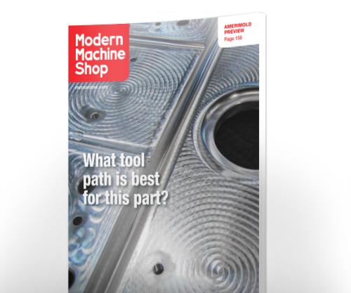
Constant-Chip-Load Machining Yields a Better Tool Path
With its in-house R&D program, this aerospace shop seeks to be a leader, not a follower, on the path to innovation in advanced manufacturing. Finding and embracing a better way to generate tool paths for highly efficient and economical metal removal is a prime example of the value of this program.

This was the cover story for Modern Machine Shop's June 2016 print issue. Subscribe here.
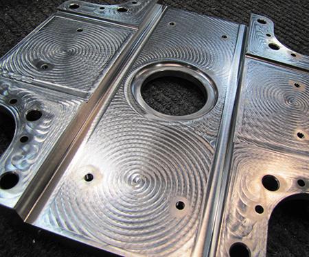
Only the play of light on the surface of this titanium aerospace part can reveal the telltale tool marks created by the programmed paths of the milling cutter. The apparent patterns reflect the motions that maintain a constant chip load on the cutting tool and follow other rules applied by the CAM software. This part weighed about 70 pounds before machining, but only 17 when completed
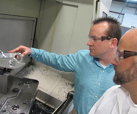
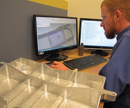
ADEX’s Charles Anthony and Chris Kozell, a Mastercam strategic accounts specialist with CNC Software, discuss some of the features of an aluminum landing gear component, which is machined on one of the shop’s five-axis Variaxis machining centers from Mazak.
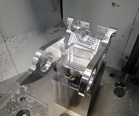
This part is a good example of tool paths prepared with the Dynamic Motion option for certain roughing and finishing operations. Several critical part features, including all eight bored holes, must be within 0.001-inch true position to one another.
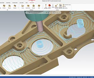
CNC programmer Dean Shaffer-Johnson studies a simulation of the tool paths used to machine a structural component for a commercial airliner. The finished aluminum part on his desk shows the thin walls for which constant-chip-load machining is especially beneficial because it avoids heat-induced warpage. The walls and floor of the pockets are about 0.080 inch thick.
In Mastercam CAD/CAM software, the Dynamic Motion programming option enables the user to enter specific values for the machining parameters that will govern its unusual toolpath algorithms. These algorithms include provisions for maintaining a constant chip load, a machining strategy that ADEX cites as highly efficient in metal removal while prolonging tool life. Determining the best input values for this shop’s mix of machining centers and preferred cutter styles was the focus of one of its major R&D projects.
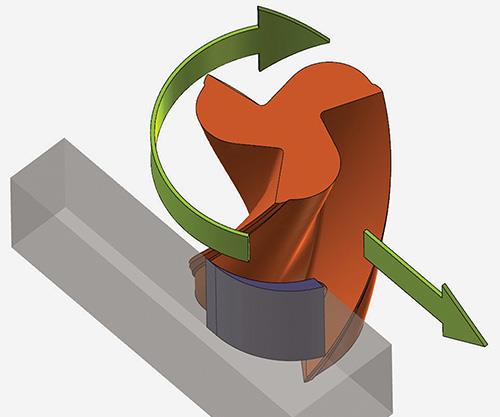
To maintain a targeted chip thickness, smaller step-overs require a higher feed rate, but can yield higher metal removal. Dynamic Motion applies this rule as it generates a kind of trochoidal tool path within boundaries defined by part geometry.
Mr. Anthony notes that cutting with the full length of a milling cutter economizes tool usage. This is another benefit of constant-chip-load machining.
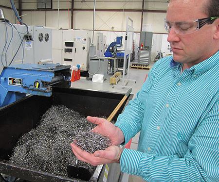
The long, skinny chips produced by constant-chip-load machining can be easily flushed from the workzone and are less likely to clog the chip conveyor.
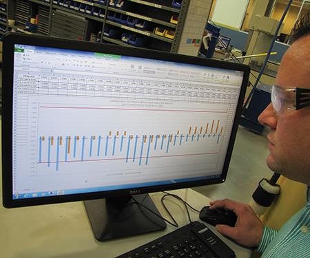
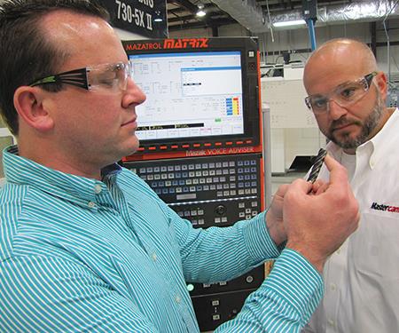
Mr. Anthony checks a comparison of inspection results from the on-machine probing and the shop’s coordinate measuring machine (CMM). Spindle-probe measurements (in blue) and CMM measurements (in gold) vary by no more than 0.0005 inch, ensuring that machining operations can be reliably verified in process using automatic probing in the lights-out mode.


“We call it constant-chip-load machining,” Charles Anthony says, referring to one of the CNC programming techniques that ADEX Machining LLC fully embraced after making it a focus of the shop’s in-house R&D program. Mr. Anthony, who is the director of engineering and operations at this 30-person shop in Greenville, South Carolina, has been promoting this concept of “job shop R&D” for several years, because he believes it gives ADEX a jump on new technology. He has seen this program (unusual for a small machining company) lead to a number of processes or capabilities that might not have been introduced there in time to get ahead of the curve on leading technology trends.
He singles out constant-chip-load machining as a prime example of R&D, because he is sure its benefits would not have been as substantial or pervasive without the R&D program to give it a boost. In the case of constant-chip-load machining, ADEX had to delve deeply into the performance characteristics of its preferred cutting tools as well as get acquainted with the kinematics of the multi-axis CNC machining centers and vertical turning lathe on its shop floor.


What Mr. Anthony calls constant-chip-load machining is one of the most important principles that underlies the Dynamic Motion option for generating tool paths in CNC Software’s Mastercam CAD/CAM software. Because ADEX has taken the time and effort to thoroughly master how to apply this option for best effect when programming complex parts in titanium and other super alloys, it has provided significant improvements in productivity and tool life across a range of workpiece types involving almost every machine tool in the shop.
“A better understanding of the cutting tools we use and how our machine tools behave helped us get more out of this approach to generating tool paths,” Mr. Anthony says. This knowledge was essential to determining the precise chip-load values that the Dynamic Motion option needs as input to create the rather unusual tool paths that deliver what Mr. Anthony has found to be very productive results.
To be clear, Dynamic Motion applies many other rules to toolpath generation in addition to maintaining a constant chip load, but following this principle is probably its greatest departure from traditional approaches, including those based on constant cutter engagement. “Mastering the concept of constant-chip-load machining was the key to unlocking its full potential at ADEX,” Mr. Anthony explains.
“We routinely see tool life last two times longer and sometimes as much as five times longer, and we know our tool paths will protect the tool and part from damaging conditions experienced with other conventional types of tool paths,” he says. Of even greater benefit are substantial reductions in cycle times. “We usually get 20- to 40-percent higher metal-removal rates, especially during roughing, because the tool paths use the full potential of a cutting tool very efficiently,” he adds. Plus, good tool paths have helped ADEX successfully machine complex workpieces to tight tolerances in difficult-to-machine materials, because consistent, precise results in roughing using this programming option virtually ensure error-free finishing operations (which may also benefit from using this programming option.)
Of course, ADEX’s R&D program has not been restricted to making the most of techniques such as constant-chip-load machining. Establishing a practical approach to automatic and reliable on-machine probing for lights-out operation is another example. “All of these R&D efforts hinge on the same principles. We seek out new ideas, learn as much as we can, develop creative ways to apply them, and try to discover new and different directions that go beyond what other shops are likely to do. This is the only way to stay ahead of the pack,” Mr. Anthony concludes.
An R&D Background
ADEX’s venturesome entrepreneurial spirit can be traced to its startup in 2007 as a shop specializing in five-axis machining. The founders, who have since moved on to other ventures, wanted to make the leap to advanced machining in a single bound. When Mr. Anthony joined the company in 2012, he brought with him almost 25 years of experience in CNC machining (including 10 years in five-axis machining), plus a background in process engineering and operations management. He was familiar with the other manufacturing technology in place at ADEX, which includes vertical turning, wire EDM, CAD/CAM and a computerized coordinate measuring machine. Mr. Anthony’s prior experience also involved a solid grasp of lean manufacturing and Six Sigma process improvement.
This combination of practical experience and theoretical knowledge helped Mr. Anthony give ADEX a firmer footing on its path to steady growth as a business, along with more certain achievement of its ambitious goals for technical excellence. Under his leadership, however, the mission of the company remains the same, that is, to apply advanced manufacturing technology to the 24/7 production of complex aerospace, defense and energy components consisting of superalloys such as Inconel, titanium, and other high-nickel or cobalt-based materials. “Because we approach every job with the standards and discipline expected of aerospace work, we’re perfectly comfortable being called an aerospace company, although about 35 percent of our revenue comes from outside this industry. Our biggest customer does build airplanes, however,” he says.
One of the things Mr. Anthony learned from an earlier stint with a large aerospace firm in his home state of Georgia was the importance of exploring new technology and giving it a try—not when this technology had become safe, easy and was in everybody’s shop, but while it was still taking shape, proving itself and finding direction. Although this former employer had the resources to engage in an R&D program on a large scale, Mr. Anthony recognized that the concept could be pursued in a company the size of ADEX as well. It did not have to be a formal program with a rigid time frame, but could follow a freer approach based on an ongoing commitment to devoting as much available time as possible to a specific goal or targeted benefit.
One of the first opportunities to take this approach arose when ADEX was introduced to the Dynamic Motion option in Mastercam by a programmer who joined the staff a few years ago. He had used this software feature to program the roughing operations for an aircraft bulkhead, thus bringing the cycle time down from 30 hours to 13. This report certainly got the attention of Mr. Anthony and his small group of programmers. Especially encouraging was news that the thin floor and thin walls of this bulkhead did not undergo any of the warping that can occur when machining forces create stress or heat from aggressive metal-removal processes.
Although ADEX had long been a user of Mastercam, the Dynamic Motion option had been neglected. Now the shop wanted to take a much closer look. Shortly thereafter, a few demonstrations on test workpieces created some distinct impressions. Dynamic Motion tool paths did not look like any tool paths the shop had used before. The cutting tool seemed to be swirling in and out of contact with the workpiece in moves that appeared to be inefficient and almost erratic.
The stepovers and stepdowns called out values that departed from usual practice in roughing. The stepovers were usually well below the radius of the tool. Stepdowns were allowed to be the full length of the cutting flute on a carbide milling cutter—another reason to raise eyebrows. In addition, feed rates and spindle speeds calculated by the software were startlingly high. “We were almost afraid to take these programs out to the shop floor at first,” Mr. Anthony recalls. However, the test cuts consistently showed very positive results.
In fact, the results were so promising that Mr. Anthony made a commitment to finding out as much as he could about this option and how it could be applied to the most challenging workpieces for which ADEX customers were requesting bids. This R&D effort would stretch over the next two years. “We were never not working on the application of this toolpath strategy. It became a habit to look at what applying this option would give us whenever roughing operations were a deciding factor in how to process a part,” Mr. Anthony says.
Constant Chip Load Is the Key
“Early on, we learned that Dynamic Motion was designed to create tool paths that resulted in parameters assuring a constant chip load on the cutter. The chip load that it keeps constant, however, is a value that tends to favor high feed rates and small stepovers, but maximizes metal removal. The idea is to take light cuts very rapidly under conditions that are best for the particular cutting tool and machine tool,” Mr. Anthony explains. He adds that there is a lot more to what Dynamic Motion does when generating a tool path, but constant chip load is a basic principle underlying its algorithms.
It also became clear that entering the correct values for the variables with which this software needed to work could not be based on guesswork. “That’s when the R&D project started to really look like R&D. We set out to develop our own calculator to generate those values, based on tables of results gathered from test cuts on each machine, using different materials and different styles of cutters,” he says.
The focus of this research centered on determining what chip load was the most productive yet safest for each combination of cutting tool and machining center. Generating the tool paths and corresponding depths of cut and feed rates to maintain that target chip load was taken care of by the software. Following is a summary of the theory behind what Mr. Anthony was up to in this research.
When a round, fluted cutter rotating at a certain speed contacts the workpiece, the sharp edges of the flutes form chips as the material is cut away. The size of these chips depends on how much of the cutter is in contact with the workpiece. The thickest chip formed is at 50-percent stepover—the radius of the cutter. When stepover is smaller than 50 percent, the chip formed will be thinner than what it would be at 50-percent stepover. As the degree of contact gets smaller and smaller, the resulting chips will be thinner and thinner in proportion. This effect is known as radial chip thinning.
Of course, making thick chips removes more material than making thin chips at the same rate. However, there are many reasons why making thick chips may be less desirable than making thin chips. For example, the cutting tool may not have the strength, sharpness and other characteristics to cut at its full radius. In that case, thinner chips will have to do.
Another important fact is that the metal-cutting/chip-making process always creates heat. Most of this heat is localized in the chip itself, but the workpiece and the cutting tool may absorb some of it. Thicker chips can carry off more heat than thinner chips simply because thicker chips have more mass to hold the heat. When thinner chips are being produced, producing them faster by increasing the rotational speed of the cutter and/or the forward motion (feed rate) of the cutter in the direction of the cut can prevent heat from being transferred to the workpiece or cutter. This prevents them from reaching a damaging temperature.
Naturally, spindle speed and feed rate are limited by the capability of the machine; faster spindles and more powerful axis drives can do a better job of producing thin chips rapidly, thus compensating for both lower metal-removal capacity and the lower heat-removal capacity of the chip.
Then there is the hardness and other properties of the workpiece material to consider. Spindle speed, feed rates, depth of cut (stepover) and all of the other machining parameters have to be adjusted accordingly. Finding the right numbers for calculating the best machine settings became the goal for ADEX’s constant-chip-load research project.
A Calculated Success
Eventually, Mr. Anthony and his team developed a calculator by which programmers can compute the best values for chip load and the other variables required for input when using the Dynamic Motion option. He considers this calculator a proprietary development for ADEX—a kind of trade secret—although he readily concedes that the recent releases of Mastercam have made it easier for other shops to plug in very workable Dynamic Motion values based on their own homework.
“We’ve just taken this homework to a higher level so that our calculator gives us a big head start in applying constant-chip-load machining very effectively,” Mr. Anthony says. “We can use the calculator to check different input values to see which combination gives us the most productive chip-load value.” He considers Dynamic Motion a tool to leverage the cutter technology that is out there today. For this reason, the shop is always looking for new products from cutting tool developers, as well as continuing to learn more about the performance of the machines in the shop.
Mr. Anthony summarizes some of the other findings or observations that have come out of this intense research on Dynamic Motion:
-
It’s not just about constant chip load. The software calculates changes in material conditions during the metal-removal process to adjust step-overs based on remaining material, and even feed rates for microlifts designed to avoid dragging. This stock awareness is critical to keeping tool paths safe yet productive.
-
The software keeps a cutter out of contact with the workpiece when the cutter is not actively cutting chips. For example, when the cutter is circling back to re-engage the workpiece, the Z axis is programmed to lift the tool off the floor of a pocket by 0.001 to 0.010 inch. These so-called microlifts prevent frictional rubbing that can heat and warp thin-floored workpieces as well as dull the bottom of the cutting tool.
-
ADEX has found that the software enables the shop to use smaller, less expensive carbide cutters for more economical metal removal. “Sometimes part processing is more profitable when you are not trying to maximize metal-removal rates,” Mr. Anthony notes. Plowing through material as fast as you can is rarely the smartest strategy, he says.
-
“With constant-chip-load machining, we can effectively machine titanium on our older machining centers that are not as powerful, rigid or as accurate as our five-axis machining centers,” Mr. Anthony says. This is possible because the chip-load values entered for these machines take these characteristics into account. “We get a safe tool path, and even if productivity is not as high, we can have roughing operations completed by the time the five-axis machines are available for finish machining. This frees up our most valuable machining assets for the most critical, close-tolerance work,” he adds.
-
Dynamic Motion is not always the best option. A traditional contouring tool path may be more than adequate when roughing operations are not a substantial portion of the process plan. Near-net -shaped forgings and pockets with irregular geometry are examples. “But we always look at the results as if we had applied the algorithm. At the least, it’s a useful learning experience, a valuable experiment,” Mr. Anthony notes.
-
Constant-chip-load machining produces chips that are consistently alike in size and shape—usually long, lightweight shavings that look like tightly wrapped foil. Because roughing parts from solid billets can generate high volumes of chips, the consistently skinny shape of the chips aids in evacuation and prevents clogs in the chip conveyor.
-
Toolpath simulation is essential. Mr. Anthony prefers the simulation feature in Mastercam to third-party simulation software because it is fast, highly detailed and very accurate. “Simulation gives us the confidence to hit the start button without worries and without time wasted dry-running a program on the shop floor,” he says. However, he cautions that no matter how good the simulation is, the user needs a trained eye to look for subtle things that can be a problem when chips, not pixels, are starting to fly.
-
On-machine probing is another requirement for leveraging constant-chip-load machining, because it enables roughing operations to proceed directly to finishing operations without interruption. “After roughing the part, we can probe the workpiece and automatically adjust tool offsets for finishing operations,” Mr. Anthony explains. But getting to the point where this approach was effective and reliable was neither simple nor quick. In fact, CAM-driven in-process gaging became another major (and highly successful) R&D project for ADEX.
The Most Productive Tool that Doesn’t Cut Chips
The impetus to forge ahead with in-process gaging emerged several years ago when ADEX launched a comprehensive time-study analysis of its manufacturing processes. One of the results was particularly startling. The shop was consistently losing 15 to 50 percent of available production time because machines were paused in the M01 (optional stop) condition. “ADEX makes both large and medium-sized close-tolerance parts, ranging in value from $5,000 to $150,000. Our CNC programmers insert M01 codes into their programs, instructing and requiring machinists to inspect the part and cutting tool to ensure everything is OK and that we are not drifting into conditions that could result in scrap,” Mr. Anthony explains.
These optional stops were costly. Because machinists usually tend more than one machine at a time, dealing with a machine in the M01 mode may not happen promptly. Likewise, resolving the issue behind the stoppage can mean a lengthy delay. Checking a workpiece dimension or the condition of a cutting tool may involve several steps requiring cautious judgment about a decision to recut or not, or move the part to the CMM for inspection, and then setting it back up on the machine.
“This approach can be a big problem when you are dealing with a 0.0001-inch tolerance,” Mr. Anthony points out. “These manual interventions, in addition to being very time-consuming, open the door for human error that can inadvertently introduce the very process imperfections that the optional stop was intended to prevent,” he concludes.
The solution ADEX first envisioned was to use the spindle probes on its five-axis machines to measure parts at specified points during machining to verify that dimensions are not drifting out of specification and to adjust tool offsets to compensate without interrupting the manufacturing process. However, the shop found this approach impractical at first. It required the CNC programmer to be well-versed in metrology or to work with a measurement system programmer to develop in-process gaging routines.
In 2014, when CNC Software introduced the Productivity Plus add-on for Mastercam, ADEX acquired it right away and began experimenting with it. This add-on enables the CAM programmer to create and call up Renishaw probing macros within the Mastercam programming session. At first, the initial release of the add-on proved somewhat difficult to apply on ADEX’s complex machining centers. Subsequent releases of the programming software and the add-on resolved these snags, however. The shop soon established a goal of implementing it on all of its Mazak five-axis machining centers for complex machining operations, as well as on its three-axis mills and large VTL.
At this point, ADEX embarked on a one-year R&D project to apply this technology across the aerospace, defense and energy facets of the business. “We envisioned the potentially enormous benefits of in-process gaging and made it a priority. We also enlisted our Mastercam reseller, Barefoot CNC, as a partner in this project,” Mr. Anthony says. The reseller co-developed and installed a postprocessor for the add-on while soliciting substantial programming and testing support from Mastercam’s Manufacturing Lab in Tolland, Connecticut. The reseller also trained the CNC programmers and machinists in appropriate use of the add-on and postprocessor.
In October 2015, the five-axis machining programs with in-process gaging were proven to the overwhelming satisfaction of customers on three of the five-axis Mazak machines, Mr. Anthony reports. “In one particular case, 75 percent of process downtime has been eliminated by automating in-process gaging,” he says. He estimates there will be a 25- to 40-percent improvement in productivity, as well as 100-percent product acceptance as in-process gaging is implemented on many of the component details and assemblies running across all of the shop’s machine tools.
A Growth Path for All
Mr. Anthony believes it is a mistake that many shops do not allow their engineers and machinists enough time to do what he calls research and development. “Owners and managers want to cut parts and ship them right now. Their philosophy insists that we don’t have time for R&D or that we will do it later,” he says. In rebuttal, he points to ADEX’s experiences with constant-chip-load machining and in-process gaging as examples of how important an in-house R&D program can be. “We give our engineers and machinists the time to experiment, dream and brainstorm in order to make the impossible become possible. Some of those things are helping us carve huge productivity gains out of our manufacturing operations,” he says.
The company benefits, for sure, but so do shop employees, because they develop new skills, work more closely as a team and increase their earning power, he says.
Finally, Mr. Anthony likes to hint about some insights and discoveries resulting from ADEX’s R&D programs that he now considers essential secrets to the shop’s success. But his invitation to other shops is to follow ADEX’s lead on a similar path to make their own discoveries and develop their own competitive advantages: “We’ve found ours and have more to come. Be inspired to go out and find yours.”


Related Content

Best Practices: Machining Difficult Materials
Cutting hardened steel, titanium and other difficult materials requires picking the right tools, eliminating spindle runout and relying on best practices to achieve tight part tolerances.
Read More
Watchmaking: A Machinist’s View
Old-world craftsmanship combines with precision machining on a vertical machining center and Swiss-type lathe to produce some of the only U.S.-made mechanical wristwatch movements.
Read More
Fearless Five-Axis Programming Fosters Shop Growth
Reinvestment in automation has spurred KCS Advanced Machining Service’s growth from prototyping to low-and mid-volume parts. The key to its success? A young staff of talented programmers.
Read More
5 Tips for Running a Profitable Aerospace Shop
Aerospace machining is a demanding and competitive sector of manufacturing, but this shop demonstrates five ways to find aerospace success.
Read MoreRead Next


3 Mistakes That Cause CNC Programs to Fail
Despite enhancements to manufacturing technology, there are still issues today that can cause programs to fail. These failures can cause lost time, scrapped parts, damaged machines and even injured operators.
Read More
The Cut Scene: The Finer Details of Large-Format Machining
Small details and features can have an outsized impact on large parts, such as Barbco’s collapsible utility drill head.
Read More