
Creating Machine-Specific Tool Paths
A new CAM capability takes a snapshot of an individual machine’s performance characteristics and uses the information to tailor an optimized tool path for that specific machine.
.jpg;width=70;height=70;mode=crop;format=webp)

This atypical tool path is highly flavored by the individual characteristics of the specific machine that will run the job.
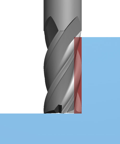
With conventional roughing strategies, the tool uses a modest axial depth of cut—typically 10 to 15 percent of the tool diameter. Conversely, Vortex uses a 2×D to 3×D depth of cut. It can do this because it never exceeds the optimal engagement angle with the material. With this method, tool wear is spread over a larger surface area, which extends tool life.
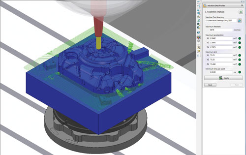
After users enter information such as machine model, control type and maximum feed rate, MachineDNA generates the G code for the diagnosis tests.
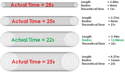
MachineDNA determined that for Delcam’s DMG DMU160P machine with Siemens 840D control, the minimal trochoid radius that could be achieved while maintaining a consistent feed rate of 10,000 mm/min. was 12.84 mm. Using this minimum radius yields a shorter tool path and faster cycle time.
Vortex broadly follows the shape of the part and only periodically introduces trochoidal motion to clean up the shape and maintain the optimal engagement angle.


Some CAM systems offer toolpath strategies that ensure a consistent load on a tool by controlling its engagement angle with the workpiece. Using this approach, the tool isn’t driven into internal corners where its engagement angle (thus, the force exerted upon it) greatly increases.
Delcam has recently developed a roughing strategy designed for solid carbide tools it calls Vortex that combines consistent tool engagement with a step-cutting strategy already available in the company’s PowerMill CAM software. With this approach, the tool does not step down immediately after each subsequent pass. Instead, extra cutting moves are added, working from the bottom of each step upwards. As a result, the initial cutter can take a much deeper axial depth of cut and remove a greater amount of material, minimizing the amount of subsequent rest roughing that’s required. Depending on the geometry of the part, the overall machining time can be reduced by as much as 60 percent, the company says. Vortex will be included within the soon-to-be-released PowerMill 2013 as well as many of the company’s other CAD/CAM offerings.


On its own, this certainly seems to be a viable, high speed roughing strategy. However, as with other CAM-generated tool paths, it’s generic. That is to say, it can be used to drive pretty much any suitable CNC machine once the appropriate postprocessor is written. There is a point, though, at which the operational limits of a machine and its control come into play. For instance, a machine simply might not have the ability to maintain the programmed feed rate that would otherwise result in optimal performance. In addition, controls differ in terms of their processing speed, high speed machining parameters and method for handling arc/line transitions among other characteristics. This spurred Delcam to look more closely at how the differences between individual machines, even machines that are very similar, affect the overall speed and effectiveness of a CAM-generated tool path.
The result of these efforts is MachineDNA, a technology the company developed more or less concurrently with Vortex. (Patents are pending for both offerings.) Directly integrated into a CAM system such as PowerMill, MachineDNA enables the CAM system to gather data from a specific machine to establish a performance baseline, and use that information to create an individualized tool path shaped by the machine’s condition and capabilities. By learning and applying a machine’s own traits, different, yet effective tool paths can result even though the same overall strategy (i.e. constant engagement angle) is applied.
Individualized CAM
Simply put, MachineDNA aims to determine what type of tool path a machine “enjoys” so the CAM system can generate such a path. Through a series of simple axis motion tests in which no actual cutting is performed, a machine defines its own capabilities. These tests need not be performed every time a new tool path is created—only when configuring a new machine or after a machine has been serviced or upgraded.
To run a test, users enter basic information such as model of machine, type of control and maximum feed rate into a simple interface within the CAM system. MachineDNA automatically generates the G code that drives the machine through the exercises. During testing, data is continuously fed back and stored within a machine-specific file that the CAM software will access each time it creates a new tool path for that particular machine.
Testing reveals a handful of key performance characteristics. These include the optimal trochoid size for a given feed rate, the machine’s preferred point distribution along curves and the most effective manner for moving through arc/line transitions. These attributes would be difficult if not impossible for even an experienced programmer to accurately identify for a specific machine.
In one exercise, the machine is directed to make a series of circular movements to determine the minimal trochoid radius at which the machine can maintain the programmed feed rate. For a trochoid radius that’s smaller than optimal, the machine typically won’t be able to maintain the programmed feed rate. Conversely, the machine might be able to maintain the programmed feed rate using a larger trochoid radius, but a bigger radius equates to a longer tool path and longer cycle time.
Testing also determines the optimal point distribution to match a machine’s control capabilities. Envision a simple oval with two lines and two arcs. The CAM system might output this arrangement as two lines and two arcs; leave the lines as they are, but linearize the two arcs for a smooth, even point distribution; or redistribute points at appropriate intervals around the entire oval shape. Based on testing performed on a range of controls, MachineDNA takes into consideration the characteristics of the control as it determines the most appropriate point distribution along the tool path. It also accounts for the control’s processing speed so as not to feed a slower control too many points, which could potentially cause stuttering due to data starvation.
Finally, when a tool goes from a straight line into an arc, some controls will dwell the tool slightly at the point of the transition. These dwells must be eliminated to maintain the programmed feed rate throughout the entire tool path. In understanding the idiosyncrasies of various controls, MachineDNA provides the data that enables the CAM system to generate an optimized tool path that accounts for such control peculiarities.
Future Applications
Initially, MachineDNA will be available for use only with the Vortex roughing strategy. This will be available to customers with the release of PowerMill 2013 first, then in Delcam’s other CAM systems. However, the company plans to apply its machine diagnostics technology in other ways. It may be used to generate more effective five-axis tool paths, because the interaction between linear and rotary axes is complicated, and the machine’s performance can be affected by a greater number of variables. In addition, MachineDNA data may prove helpful in increasing the accuracy of machining time estimation.
The company says the baseline testing that MachineDNA performs is not designed to be a tool for machine benchmarking or direct comparison. In fact, the data gathered from machine tests doesn’t lend itself to any such assessment. Insetad, it simply enables a machine to achieve a higher level of its potential performance by using tool paths engineered to work in concert with a machine’s capabilities.
Sidebar: Minimizing Trochoids
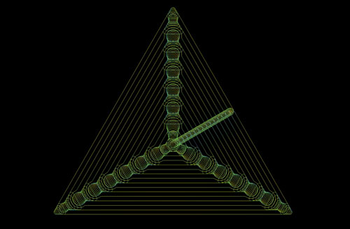
Trochoidal movements are sometimes introduced to maintain a consistent engagement angle throughout the entire tool path. Vortex, however, aims to minimize the amount of rolling, trochoidal moves because the tool doesn’t cut anything for approximately half of each circle of motion. Instead, it broadly follows the shape of the part and only periodically introduces trochoidal motion to clean up the shape and maintain the optimal engagement angle. This can be seen in the tool path shown in the bottom image, in which the patterns of corner approaches are not regular. Trochoidal motion is applied only when absolutely necessary to maintain a controlled engagement angle. This differs from a conventional approach in which the tool starts in the center and spirals out until it reaches the edges of the triangle before using large trochoidal movements to work into the corners.
Delcam has developed a guide of parameters for various tools and workpiece materials because conventional roughing parameters aren’t appropriate for use with Vortex. This will enable users who aren’t familiar with controlled-engagement-angle tool paths to get their cutting parameters in the ballpark as they dial-in their process.


Related Content

CAD/CAM System Requirements: An Overview
CAD/CAM programs are among the most demanding kinds of computer software. Smooth operation requires careful consideration of computer specifications.
Read More
Can ChatGPT Create Usable G-Code Programs?
Since its debut in late 2022, ChatGPT has been used in many situations, from writing stories to writing code, including G-code. But is it useful to shops? We asked a CAM expert for his thoughts.
Read More
Large-Format Machining With Small Cutting Tools and Dynamic Motion
Napoleon Machine, a defense contractor that provides parts for the M1 Abrams tank, recently took advantage of a CAM feature that allowed the company to streamline its cutting strategies and program offline. Here’s how the shop cut cycle times nearly in half with its large-format five-axis machining operations.
Read More
Grinding Simulation Enables Growth in Custom Tooling
Simulation software both streamlines Gorilla Mill's grinding machine setups and speeds up the company's tooling design and verification processes.
Read MoreRead Next

The Cut Scene: The Finer Details of Large-Format Machining
Small details and features can have an outsized impact on large parts, such as Barbco’s collapsible utility drill head.
Read More
3 Mistakes That Cause CNC Programs to Fail
Despite enhancements to manufacturing technology, there are still issues today that can cause programs to fail. These failures can cause lost time, scrapped parts, damaged machines and even injured operators.
Read More
