
Custom Fixtures Off The Shelf
Using a new software system, custom 3D fixtures can be generated automatically. The software creates 2D fixture components that can be laser cut and assembled for a fraction of the cost and in significantly less time than other methods.


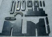
The contours of the supporting pieces are created from CAD data of the workpiece. These components are nested in sheet metal and cut using a laser machine.
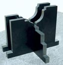
The main components are assembled together. Generic components, such as toe clamps and hold-down brackets, are kept in the database for repeated use.
Using a new software system, custom 3D fixtures can be generated automatically. The software creates 2D fixture components that can be laser cut and assembled for a fraction of the cost and in significantly less time than other methods.
Creating a workholding fixture for workpiece blanks that can’t be held in standard vises or chucks can be an expensive bottleneck for job shops. Often a job is a one-time contract, and making custom fixtures for it is economically questionable. The time involved to have fixtures made is also a consideration, with delivery pressures being a large part of getting a given job.
Most of us know Mazak as a manufacturer of machine tools for metalcutting applications. The corporation also has a metal fabrication side of the business for cutting sheet metal. For sheet metalcutting shops that process 3D fabricated workpieces, holding the work is a concern, just as it is in chip cutting shops. While cutting pressures for laser machines are different than for machining, the need to securely support the work is analogous for both metalworking processes.


A new software package, developed by Mazak Laser for generating custom fixturing for laser cutting applications, can also be used to generate workpiece-specific fixtures for metalcutting applications at a fraction of the cost and time of having special fixtures built.
The software, Space CAM, basically takes what was once the manual process of building a fixture and automates it, according to Tim O’Donnell with the company’s technical services department. The process begins by importing a solid model or surface model CAD file into the software. The CAD model is then oriented in space relative to the machine base or table that will support the fixtured part.
Work zone parameters in X, Y and Z axes are assigned to fit within the cutting area of the laser machine. The programmer is free to choose cross-sections of a fixture grid, generated by the software, that best support the part and select those lines on the screen.
From these grid lines, the programmer builds a 3D fixture from grids that will be cut into 2D sheet metal parts with contours that conform to the geometry of the CAD model. Generic tabs and hold-downs are captured in the software database so that they do not need to be created from scratch each time.
From the 2D plates, a tool path for the laser is generated for the laser machine’s CNC to cut the fixture components. Automatic nesting of the components is also part of the software. To avoid any processing glitches, the cut path can be run in simulation for interference or other problem areas. Any edits to the cutting path or the fixture geometry can be performed at the point of interference.
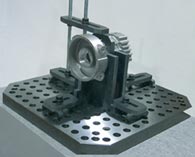
The laser-cut 2D plates are assembled and ready to hold the workpiece for laser cutting or machining. The programming time for a fixture is accomplished in a fraction of the time needed by previous methods. According to Mr. O’Donnell, some customers have seen start to finish for a 3D laser part reduced from 4 to 5 days to 5 to 6 hours for job turnaround.
If fixture generation is a bottleneck in your shop, it might be worth finding a sheet metal shop with this capability.


Read Next

The Cut Scene: The Finer Details of Large-Format Machining
Small details and features can have an outsized impact on large parts, such as Barbco’s collapsible utility drill head.
Read More
3 Mistakes That Cause CNC Programs to Fail
Despite enhancements to manufacturing technology, there are still issues today that can cause programs to fail. These failures can cause lost time, scrapped parts, damaged machines and even injured operators.
Read More
