Don't Move That Mold
A portable measuring arm allows 30-ton molds to be measured without having to be moved.


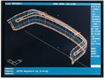
To measure a feature in the channel that holds the rub strip, the operator touches it with the probe and presses the buttons on the handle. The software then compares the measured points whth the corresponding points that are in the CAD model.
Proper Mold's quality assurance department checks the mold's surfaces directly against the original customer-supplied CAD file after applying the appropriate shrinkage factors.
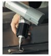
The measuring arm's six degrees of freedom provide the flexibility to reach all of the mold's features and approach them from any angle.
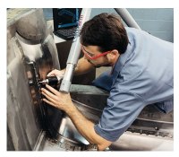
Steve Carbary checks the slots that will create the features necessary for connecting a mating part to the lower portion of the fascia.
The measurement of large molds can be a cumbersome and expensive task at our shop, Proper Mold and Engineering Inc. (Warren, Michigan), a global supplier of plastic injection molds for automotive and other industries. Our shop designs, machines, and assembles intricate tools for producing plastic parts as small as electrical components and as large as automobile fascias.
Each half of a fascia mold can weigh as much as 60,000 pounds, which is too heavy and sometimes too large for the traditional CMMs in the Warren facility. The most we can put on our CMMs is 20,000 pounds. Yet, because dimensional measurement is a cornerstone of quality control and tool-certification programs, the company needed a way to measure these large molds to less than 0.25 mm on a regular basis.


Quality and precision are an integral part of the manufacturing process at Proper Mold's two modern plants and rapid prototyping facility in metropolitan Detroit and at the new manufacturing facility in Anderson, South Carolina. In Warren, for example, dedicated, skilled craftsmen work in a clean, bright shop and have access to some of the largest and most advanced CNC machines available today. That includes three- and four-axis machining centers (for cutting cores and cavities as well as other metal parts and graphite electrodes), wire and ram electrical discharge machines, and gun drills. The shop also uses a range of support machines including rapid prototyping equipment, laser digitizers, and several molding machines for the testing of finished molds.
Also supporting the quality effort are comprehensive inspection procedures, coordinate measuring machines (CMMs), granite surface tables, and portable inspection tools. Inspectors monitor each mold as it progresses through manufacturing; and afterward, they use CMMs fitted with touch probes to verify that the final product adheres to customer-supplied data.
In the past, Proper Mold would use one of the large milling machines to inspect the molds that exceeded the CMMs' capacities, such as those for auto fascias. The process involved creating a road map of the points to be checked by loading the mathematical data onto a CAD station and collecting X-Y-Z coordinates of each location. Once the map was ready, technicians would move the mold onto one of the milling machines, indicate it in, establish a starting location, and check each point on the map.
After collecting data with the mill, they would record each actual measurement in the column next to the one containing the coordinates from the CAD file so they could compare the two, perform any necessary calculations, and judge whether each feature was within its specified tolerance. The procedure was time consuming, and it tied up a mill for a few days when it really should have been doing what it does best, making chips.
A Faster, More Flexible Tool
For that reason, Proper Mold bought a FaroArm—a seven-axis, portable measurement arm made for three-dimensional measurements and reverse engineering by FARO Technologies, Inc. (Lake Mary, Florida). Since using the arm, the company has cut the time it takes to measure these large molds in half and has been able to greatly improve customer service in the process.
Steve Carbary uses the measurement arm to collect coordinate data as single points or as a stream of points by touching a mold with a probe at the end of the arm. Digital signal processing technology (DSP) and hybrid transducers at each of the arm's six joints report each point's position (X, Y, Z) and orientation (I, J, K).
To get the reach and flexibility necessary to measure inside large molds, Proper Mold uses an 8-foot arm in a "2-2-2" configuration (there are others available), which means it has two axes at the base, two at the arm's elbow, and two at the wrist. The arm can fold back on itself at the middle joint, letting the operator reach into the mold's cavity and around and under the various components. The arm uses precision bearings and is made of aircraft-grade aluminum, which expands uniformly throughout the working temperature range. This enables the arm to compensate for temperature automatically. On the 8-foot model that Proper Mold uses, we can get accuracies of ±0.076 mm (0.003 inch) throughout the working envelope.
A Good Fit
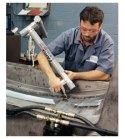
Most of Steve Carbary's work with the arm involves CAD-to-part inspection—that is, comparing a mold to a customer's CAD file. On one particular rear fascia, for example, Steve compared measured points on the mold to corresponding points on a CAD model to find out why the black rub strip was not snapping into place exactly as the customer had planned. "It was a tight squeeze to get the strip in place," he says. "So the customer's engineers were concerned about the relationship between the clips on both the strip and fascia."
He began the inspection process by importing the customer's surface model of the part into AnthroCAM, the measurement arm's 3D CAD-based software. At Proper Mold, the inspection software runs on an IBM ThinkPad laptop computer connected to the arm via an RS-232 serial port, and it regularly imports a variety of file formats—including DWG, DXF, Ford STD, IGES, and others. We prefer to import surface models, but the software can also accept wireframes.
Because the measurement software runs in AutoCAD, the inspector can apply the appropriate shrinkage factors and rotate the part into die draw position after importing the customer's surface model of the fascia. He can also use layer controls to suppress extraneous information in the file and then rotate the simplified model to find the relevant points to measure. The layer controls make setting up the job much easier, especially on molds for large parts. The files contain a lot of information that can get in the way.
The next step was to verify that the surfaces of the fascia model matched the actual surfaces in the mold cavity. Checking the cavity and core against the customer's CAD data, rather than the mold design, is a regular procedure within the inspection department. At this stage, we are concerned with whether we properly cut the surfaces that would produce the part's features.
To verify the fascia model surface, Steve chose the surfaces he would need to measure. He identified the necessary measurement points on the CAD model and saved their nominal values, which he could then retrieve on the shop floor. By preplanning the inspection routine in this way, he cut the total amount of time spent measuring the mold from eight hours to four. Preparation not only reduced the actual time spent inspecting the mold, but it also allowed Steve to become more familiar with the mold before inspecting it.
Software Streamlines The Job
After preparing the inspection routine, Steve carried the 30-pound arm to the mold, a much easier task than moving the 60,000-pound tool. The measuring software showed the selected points directly on the CAD model and, through the home-in function, guided him to each target point. Because each target point had a tolerance zone specified in advance, he needed only to move the probe to the zone to measure the point.
AnthroCAM compared the measured point to the CAD nominal surface automatically and displayed the nominal and measured values, the deviation from nominal, and any out-of-tolerance value for each measured feature in real time. To measure a hole for fastening one of the rub strip's clips, for example, Steve collected at least three points along the circumference, and the software computed the circle's size and location automatically and overlaid the feature on the CAD master for comparison. Gone was the tedious method of reading the X-Y-Z coordinates from the mill's digital readout and calculating those values by hand.
The software also made measuring on the fly easy, allowing Steve to deviate from his preplanned routine at will. Whenever he encountered a problem or saw a better way to do the job once he started, he picked new points from the CAD file and modified his routine.
By contrast, accommodating deviations from the inspection plan was not nearly as easy on a mill as it is with the measuring arm, mainly because the data were not readily accessible from the shop floor. The inspector would have to stop, find a free CAD station in the office, pull up the appropriate file, retrieve a new inspection point, return to the shop floor, and pick up on the job where he left off. This is one reason why the old method took twice as long as with the FaroArm.
After checking the relationship between the two clips, Steve found that the clearance was too small for the two pieces to mate properly. Based on these findings, we recommended welding the mold to add the necessary clearance and updating the electronic data to document the change. Once manufacturing made the repair, we rechecked the mold with the measuring arm to make sure that the alteration matched the new design.
After final inspection, Steve compiled the data and generated a report. Sometimes we use standard reports that come with the measuring software, and sometimes we use our own. It depends upon the customer. Some expect to see diagrams, others want just numbers tabulated in an Excel-type format. The software gives us the flexibility to deliver the reports as electronic files or on paper with the part measurements aligned to body coordinates to make the measurements easier for the customer to understand.
Portability Pays Big Dividends
Besides unburdening milling machines from inspection and freeing them for production, another dividend from the measuring arm comes from its portability. We can send a technician and an arm across the country, as well as out to the shop, to measure molds. Such was the case when a customer in South Carolina discovered that the front grill and logo did not fit the way its engineers thought they should. Because Proper Mold made the mold for the grill and another vendor made the logo's mold, the customer had to do some detective work to find whether the problem lay with one of the molds or with the design itself.
In such situations, the customer normally finds an outside contractor to inspect the molds. The customer's engineers suspected that the size and locations of slots for the logo were not right, so they asked us to measure the part and mold to verify it was right. The problem was that the South Carolina facility did not have the equipment necessary for checking the mold and a fixtured part.
Because customer service is an important aspect of Proper Mold's business, Steve Carbary grabbed the arm and laptop, and flew to the South Carolina facility. "I met with the customer's representative, set up the part in a holding fixture beside the mold, and measured the areas of concern as he pointed to them. This showed him that the part and mold matched the data that his company's engineers had supplied," he recalls.
When two vendors make parts that are supposed to fit together, but don't, the customer has to figure out which one is wrong. We proved in one day that the problem was not due to the way the mold was built. The error was either a mistake with the other supplier's tool or a design mismatch not caught before the customer released the data to its tool vendors.
From the customer's point of view, solving that part of the puzzle was painless and inexpensive because the company did not have to ship the mold to another location and visit an out-of-town vendor. It also meant that Proper Mold did not incur the $5,000 to $8,000 expense of repairing the mold and risk losing a customer's confidence. In fact, showing that the mold was built to print made the customer feel much more comfortable with our work.
A Tool For Encouraging Innovation
The measuring arm is also useful in giving Proper Mold a tool to inspect the increasingly more precise and complex molds our engineers are designing these days. One reason molds are getting much tougher to build and inspect is that tolerances are becoming much tighter. The average tolerance is already 0.50 mm on parts and 0.25 mm on molds, and is often much tighter on individual features.
Moreover, the trend among automakers to make fewer components puts pressure on mold makers to innovate. Among mold makers, innovation typically means adding more complex mechanisms to form more features on one part. As our designers come up with better ideas, we must also become more creative in our inspection procedures. Molds for instrument-panel bases, for example, need movable slides and lifters to form details like holes, clips, and irregular surfaces at various angles. We must remove these components to check them, which involves finding the right reference points on the detail, disassembling the mold to expose all of the surfaces that create it, and measuring each point. A mold can have five or more removable components built into it.
Innovation and competitiveness, therefore, require a flexible tool to inspect large molds and their components quickly and accurately. With the flexibility to go from fixture to fixture and to travel to molds on the shop floor and across the country, Proper Mold frees its milling machines for production and inspects its products in half the time and at half the cost.
About the author: Keith Huck is managing associate for quality and training at Proper Mold.


Read Next

The Cut Scene: The Finer Details of Large-Format Machining
Small details and features can have an outsized impact on large parts, such as Barbco’s collapsible utility drill head.
Read More
3 Mistakes That Cause CNC Programs to Fail
Despite enhancements to manufacturing technology, there are still issues today that can cause programs to fail. These failures can cause lost time, scrapped parts, damaged machines and even injured operators.
Read More