
Dynamic Motion Moves Past Old Boundaries
The Dynamic Motion option in CNC Software’s Mastercam generates tool paths by following an expansive set of rules that are different from those most CAM software has traditionally followed. The motion of the tool is not defined strictly by boundaries of the area to be machined. Instead, the rules take into consideration not only the area from which metal is to be removed, but also the changing condition of the material throughout the various stages of machining.

The rules for generating a tool path in Dynamic Motion are designed for efficient cutting, not just efficient coverage of an area set by boundaries in the part geometry. Using full flute engagement wherever possible is one rule, for example.
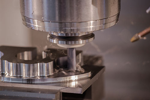
One benefit of machining with dynamic tool paths is the possibility of using one smaller carbide tool to do roughing, rest machining and finishing in a combined operation.


What happens when the programmer clicks the button to start generating tool paths in CAM software? Truth is, it’s hard for the programmer to tell what the lines of code and the algorithms they represent are going to do. The only way to accurately judge is to evaluate the results after executing the finished program. An interesting look at “what goes on inside” CAM software when it generates a tool path comes from the Dynamic Motion option in CNC Software’s Mastercam. The developers say this approach to generating tool paths is unusual because the set of rules followed by this software function are expansive and different from the rules most CAM software has traditionally followed.
Dynamic Motion was originally introduced with the X4 release of the software in 2009. First applied to 2D pocketing, this new approach set the direction for the development of additional applications in toolpath generation. The concepts of Dynamic Motion now underlie five 2D tool paths (including roughing and contouring routines), four 3D tool paths, one routine for rough turning, and two rewrites of blending and peel milling routines.


Typically, conventional CNC toolpath programs are based on bounded geometry. These programs have the tool enter the material and then set off in one direction until it encounters a wall or some other obstacle, whereupon it changes direction. The tool zigs and zags until it covers all of the area delineated by the part model, cutting whatever is in its path—whether material or air.
Dynamic tool paths make the tool act differently than expected in a conventional program. The motion of the tool is not defined strictly by boundaries of the area to be machined. Instead, the tool paths are governed by a highly engineered set of rules that takes into consideration not only the area from which metal is to be removed, but also the changing condition of the material throughout the various stages of machining. The process looks ahead to see what is coming up to modify feeds, stepovers and cutting motions in response to ever-changing material conditions as the part is being cut. The objective is to remove material more efficiently by controlling lateral forces to avoid excesses that generate heat.
Other rules that govern Dynamic Motion include:
• Minimal stepovers to avoid heat buildup and excessive lateral force.
• Smooth motions that alleviate stresses on tools and the machine (trachoids are one example).
• High spindle speeds, if available.
• Maximum flute engagement for cuts that remove the most material.
• Continual material engagement (climb milling) to minimize air cutting.
• Dynamic adjustments of stepovers to keep tool load constant.
• Entry strategies that present the tool to the material at the safest angle.
• Material “awareness” that keeps the tool in a consistent, safe cutting condition regardless of the pocket or contour geometry. It modifies the path so that chips will be the same size.
• Micro-lifts that raise the cutter away from the part’s floor or away from walls so that heat does not build up when cutting speeds are being adjusted during repositioning.
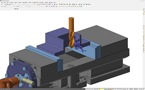
Dynamic toolpath processing has the ability to consider various alternatives about what to do next, and then make an intelligent selection based on an analysis of what impact the various options will have on the final outcome. For example, from a number of schemes for entering the part, the program selects the one that enables it to best utilize the algorithm for machining. Let’s assume it takes the tool into the more open side of the pocket. Now the tool spirals its way out—always having constant contact by climb milling to avoid the conventional back and forth—until it runs into a wall. The program has the intelligence to figure out what the next move should be for the most efficiency. Say the tool goes into the corner of the pocket. In most cases, when it runs into a wall, it will reposition itself outside of the material, because it knows where the material has been removed as well as where it remains, and it re-enters appropriately. The only time the tool is cutting air is when it is repositioning.
Likewise, whereas some programs will retract the tool to a clearance plane or a retract plane, dynamic tool paths retract only a slight distance—just enough to prevent scrubbing the part floor with the bottom of the cutter, which causes unwanted heat. In effect, dynamic tool paths know how to do little pirouettes—micro-lifts of 0.005 to 0.010 inch to keep the tool safely away from the floor of the pocket.
Developers report significant economic benefits from using these tool paths. Two and even three times faster machining rates are achievable, especially for high material removal operations such as roughing. Tool breakage and wear are greatly reduced compared to conventional high-engagement, high-torque hogging. Full-flute, higher-speed, minimal-engagement machining requires less torque and therefore consumes less energy. Smaller, less costly carbide tools can be used because lateral forces that damage them are controlled, and using a smaller tool may enable it to perform roughing, rest roughing and finishing as combined operations. Sometimes when several operations can be performed using a single, smaller tool, surface finishes are better, possibly reducing or eliminating a secondary operation such as grinding.
However, CNC Software recognized that a conventional tool path might be preferred over Dynamic Motion in certain situations, so both remain as options. The option of using dynamic tool paths is encouraged because the programming interface is simple and involves setting a few parameters from a menu. Frequently, the result is significantly higher productivity and reduced tool wear, regardless of available spindle speed at the machine tool. Even where the payback appears to be marginal, there is no reason not to use dynamic tool paths. The company says they are the most reliable, robust and capable way of machining more types of materials and geometries than any machining strategy in Mastercam’s history.


Related Content

Automated CAM Programming – Is Your Software Really Delivering?
A look at the latest automation tools in Autodesk Fusion 360 software and how forward-thinking machine shops and manufacturing departments are using them to slash delivery times and win more business.
Read More
Building A Powerful Bridge from the CAM Programmer to the Shop Floor Operator
SolidCAM for Operators provides a powerful bridge from CAM programming to the shop floor to best streamline the machine shop process with its CAM part simulation. It provides a clear picture to the operator for setup and prove-out, enables minor G-Code changes and avoids crashes, broken tools and scrapped parts.
Read More
Grinding Simulation Enables Growth in Custom Tooling
Simulation software both streamlines Gorilla Mill's grinding machine setups and speeds up the company's tooling design and verification processes.
Read More
Finally, A Comprehensive Software Solution Designed for Small Job Shops
Zel X from Siemens is an integrated software application that consolidates collaboration, design, manufacturing, and operations into a comprehensive, easy-to-use solution. From RFQ to delivery, it’s a more efficient way to handle quotes, manage jobs, make parts, and collaborate with teams of all sizes.
Read MoreRead Next

The Cut Scene: The Finer Details of Large-Format Machining
Small details and features can have an outsized impact on large parts, such as Barbco’s collapsible utility drill head.
Read More

3 Mistakes That Cause CNC Programs to Fail
Despite enhancements to manufacturing technology, there are still issues today that can cause programs to fail. These failures can cause lost time, scrapped parts, damaged machines and even injured operators.
Read More