
FEA for DFM
Shops that offer design for manufacturability advice can reduce customers’ machining cost and complexity. This shop leverages finite element analysis as part of its sophisticated DFM efforts, and this also helps in its efforts to establish long-term relationships with its customers’ engineers.
.jpg;width=70;height=70;mode=crop;format=webp)
Finite element analysis is a powerful tool for Parametric USA in its efforts to provide design for manufacturability services to help its customers to simplify their part designs for easier machining.
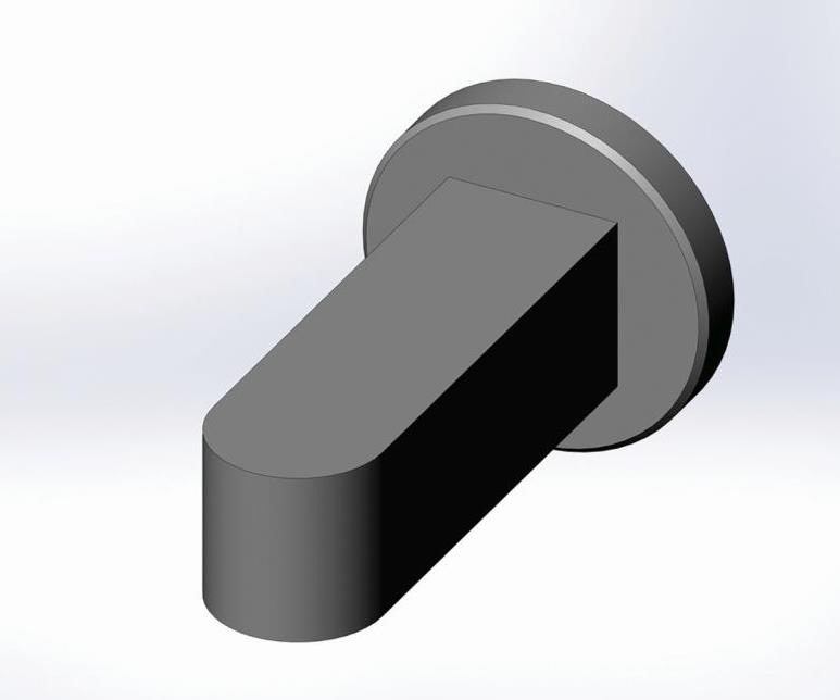
The original design for this component used a rectangular shaft.
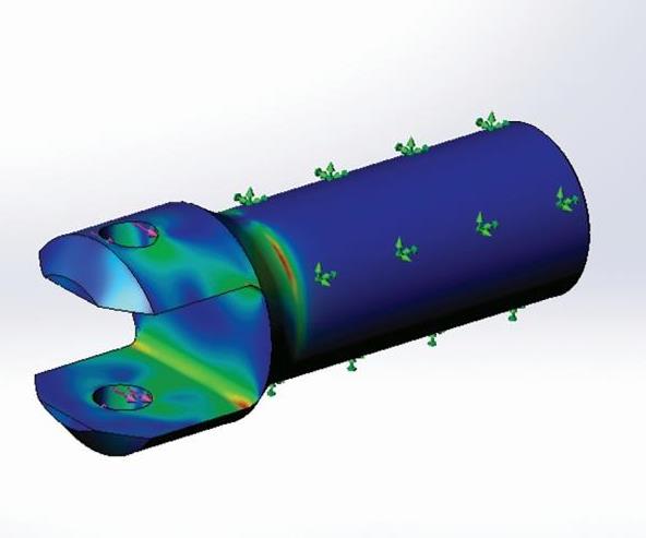
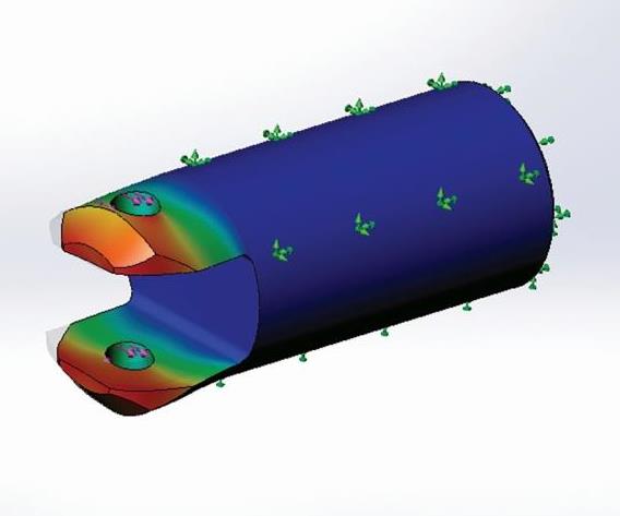
The first DFM iteration changed it to include a cylindrical shaft with bull-nose yoke, reducing manufacturing costs by 75 percent.
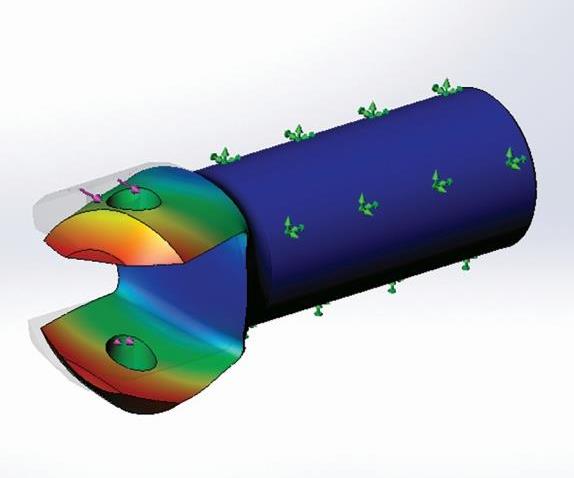
FEA showed deflection due to side loading was too much, however, so another DFM iteration was performed.
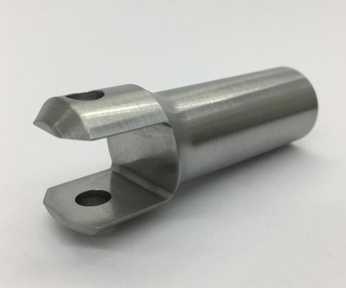
By increasing the shaft diameter to remove the bull-nose feature, turning and grinding was made simpler and faster, and an off-the-shelf slide bearing could be used. The estimated savings for 1,000 parts are approximately $33,000.
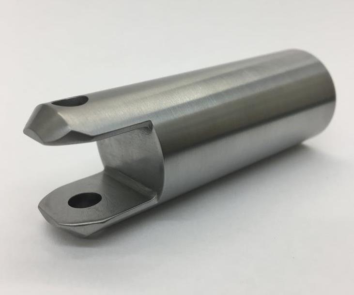
Here is Parametric USA’s final component design.
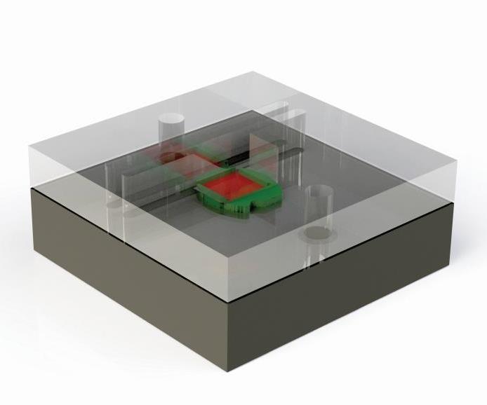
Here is an example of a fixture designed to hold a small printed circuit board that was refined using FEA to ensure it generates the appropriate clamping force for machining.
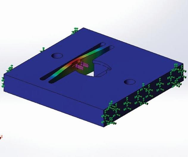
That force is generated by simple deflection of the Delrin fixture’s 0.125-inch-wide center beam feature.
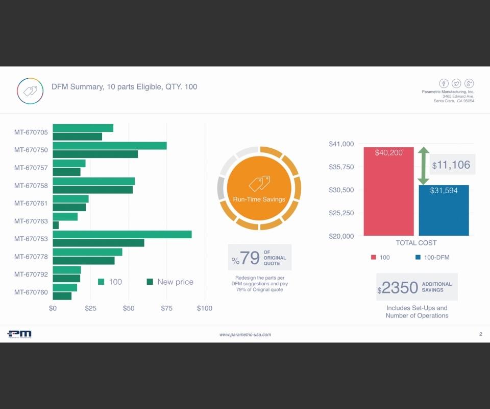
Parametric USA creates infographics such as this for its customers’ engineers that show how much those engineers have saved their companies by implementing DFM on various parts. This is the infographic it created for Mountz after the initial DFM efforts for the company’s new product.


Many leading machine shops offer design for manufacturability (DFM) advice to their customers. Modifications to a part’s overall design, certain part features or tolerances that don’t adversely affect product performance can often simplify the machining of the part, reducing overall manufacturing costs and production time.
DFM is becoming more important these days, as an increasing number of companies don’t have internal machining or manufacturing capabilities to produce their products. Thus, design engineers can’t solicit ideas from their own manufacturing experts for ways to refine their designs to simplify machining. It can also


be the case that young engineers simply don’t have much or any experience with manufacturing processes, and this can result in component designs that are either hard or nearly impossible to produce. Both scenarios lead them to rely more on outside machining vendors to provide such guidance.
In most cases, shops tap their wealth of machining experience in formulating the DFM changes they suggest to their customers. Parametric USA, a mid- to high-volume contract shop in Santa Clara, California, does this. However, it also can take DFM to the next level, applying finite element analysis (FEA) to refine customers’ part designs by taking into consideration the forces and loading conditions that will be exerted on those parts during operation, then calculating approximate values for the displacements, stresses and strains those components will experience. Using FEA for DFM in this way effectively demonstrates that the suggested design changes that will simplify part production will not cause the part to exceed operational limits or constraints.
Ryan Teixeira, company COO and certified professional engineer, says FEA capability is a differentiator for the shop. “It can be tough to convince customers that design changes can drastically reduce manufacturing costs,” he says. “However, FEA is the language of engineers; it’s quantifiable and carries weight with them. Therefore, we work hard to establish close relationships with our customers’ design engineers, realizing that FEA is just as valuable to them as our advanced machining and manufacturing capabilities.”
In fact, Mr. Teixeira says building relationships with those engineers through DFM does more than just enable Parametric USA to win new business and retain good customers. It also enables those engineers to demonstrate the value they bring to their companies by quantifiably showing how much money their refined designs have saved them. This creates a win-win-win for the shop, the shop’s customers and the customers’ engineers.
FEA as a Business Strategy
Parametric USA is an evolution of a family-owned shop that was started 30 years ago by machinist and mechanical engineer Jon Drury. The 20-person operation produces parts for a range of applications in the robotics, medical, semiconductor, fiber optic and electric vehicle industries. In-house capabilities in its 13,000 square-foot facility include CNC milling, turning and wire EDM, although Mr. Teixeira says relationships with local vendors offering processes such as grinding, lapping, brazing, silkscreen and heat treating enable it to be a full-service parts producer.
Mr. Teixeria had worked with Mr. Drury and other companies in the Silicon Valley as a mechanical engineer for 20 years before partnering with him in 2016. One of the goals in joining the company was to leverage his engineering and start-up experience into a new business strategy in which Parametric USA would target a new demographic within its customers’ operations—their pool of design engineers—in an effort to establish long-term business relationships.
“We’ve seen that it can be tough for an engineer to accept DFM suggestions offered by a machinist even if he or she has many years of machining experience,” Mr. Teixeira says. “However, I can start a conversation by explaining to an engineer how, for instance, after running an FEA model of the part, I might find that removing an internal radius that’s tricky to machine will save $1.75 per part while keeping stress concentrations in the acceptable yield range and increasing deflection by only 3 percent. By speaking the language of engineers in that way, I’m better able to start building their trust and gaining their respect. In addition, they also become more open to sharing load and force data as well as other pertinent operational information about other parts to enable me to perform FEA for DFM on those as well.”
FEA Examples: A Part and a Fixture
In short, FEA applies the numerical finite element method to calculate approximate displacements, stresses and strains a component of an assembly will experience under load during operation. It starts by dividing the component into small elements with simple geometries and defined material characteristics and boundary conditions (how they are constrained from moving). After solving differential equations for them to determine how each individual element behaves under load, the elements are essentially joined together to derive an equation that describes the entire component to approximate how it will perform under load.
Mr. Teixeira uses Solidworks Simulation 2017 FEA software, the latest version of an FEA package he began using in 1998 and continued using at a few different companies he worked for until purchasing a personal copy in 2008 when he began his FEA engineering consultancy business. “Having FEA and solid-modeling CAD in one software package makes it easier to tune design features,” he says. “In addition, a large percentage of our customers use Solidworks, so having access to their native files enables me to more easily tweak and justify specific features.”
Even with this capability, he starts by performing initial calculations (known as first-order calculations) by hand to approximate what the range of results produced via subsequent FEA calculations should span. “Setting an FEA model’s boundary conditions correctly, understanding the nature and behaviors of materials, and understanding the significance of the results requires a fundamental understanding of engineering statics, dynamics, thermodynamics and strength of materials,” Mr. Teixeira explains. “I apply this knowledge to perform first-order calculations by hand prior to using the FEA software to understand what the range of results should be. I then transition to the FEA software to reveal behaviors in part stress, deflection, weak points and so on in order to effectively tune the part design.”
Mr. Teixeira says Parametric USA has used FEA to refine the designs of multiple customer projects, although confidentiality agreements prevent him from disclosing details about many of those parts. One example he can describe in very general terms is a component of a yearlong product development effort for Mountz Inc., designer and manufacturer of fastener torque-control tools and related products located in nearby San Jose, California.
Aware of Mr. Drury’s and Mr. Teixeira’s engineering background, Mountz brought them in to perform DFM analysis of the initial design. They presented a detailed review of each part and demonstrated a potential cost savings of more than $11,000 for the first batch of 100 products.
However, after extensive testing, Mountz recognized that a major redesign was required to yield a solution that met the product’s performance requirements. Therefore, a second development effort with Parametric USA and other industry specialists was launched to pursue two different mechanical solutions. Both were developed simultaneously to converge on a design solution that never could have been realized without FEA, DFM and endless testing, Mr. Teixeira says. The goal was not only to generate a product that would be simpler to manufacture, but also to investigate different materials, surface finishes and heat-treating methods.
The component mentioned previously, which was ultimately made from 9310 case-hardened steel, proved to be one for which DFM concepts could reduce manufacturing costs. This component experiences a side load of 1,500 pounds under dynamic conditions. The initial design called for its shaft to be rectangular, which required a custom rectangular slide to be manufactured at $60. It also included an intrinsic cylindrical disk feature. These elements proved expensive to manufacture in terms of the milling time for both the part itself and the slide bearing. In addition, the component required case hardening and a 6- to 8-Ra surface finish, which was difficult to achieve given its complex geometry.
Parametric USA’s first DFM redesign separated the disk feature from the component and replaced it with an inexpensive part that didn’t require heat treating. The component’s main geometry was changed from rectangular to cylindrical, with a 0.75-inch shaft and a bull-nose yoke (see the images at the top of this article) to fit inside Mountz’s design without affecting other components. This simplified machining, in moving from a milling operation to a turning operation, enabled the use of an off-the-shelf cylindrical slide bearing and offered the possibility for low-cost, precision grinding to achieve the required surface finish. This initial step cut overall manufacturing costs for two components by 50 percent, Mr. Teixeira says.
However, using FEA, it was determined that the side load created deflection in the range of 0.0012 to 0.0015 inch, which was twice the target deflection range. Also, the bending stresses were above the fatigue strength sweet spot for this application. This called for a second DFM redesign.
Mr. Teixeira explains that, by removing the bull nose so that the entire component had an outside diameter of 1 inch, the side-load bearing area was increased and the stress concentrations were reduced. This enabled the target deflection range of 0.0003 to 0.0007 inch to be achieved while further simplifying surface grinding to attain the required finish. In addition, it enabled an off-the-shelf $10 cylindrical slide bearing to be used instead of a machined part. Machining time was reduced, too, from 28 minutes per part to 15 minutes. The potential savings in part quantities of 1,000 was estimated to be $33,000. (As noted before, two mechanical solutions were pursued by the customer, tested and vetted. This component ultimately morphed into a different version as a result of further development.)
Mr. Teixeira has also used FEA to optimize and verify designs for fixtures for tricky parts. The fixture shown at the top of this article is good example of a simple design with minimal components that he devised and then proved out via FEA. The fixture is used to secure a printed circuit board (PCB) that is machined using a 0.012-inch-diameter end mill to house an optical mirror measuring only 3 by 3 mm. With this design, the clamping of the PCB is achieved solely via the natural deflection of the fixture’s Delrin material instead of using springs, clamps or other conventional fixturing components. Two slots machined 0.125 inch apart create a beam that deflects to provide the clamping force for the PCB. Mr. Teixeira initially performed first-order calculations and determined that an appropriate force of 1 pound would be generated from 0.01 inch of material deflection. This would provide sufficient clamping force for machining without causing the PCB to deflect. He then used FEA to tune the beam width, thickness and material type to achieve the target beam deflection and clamping force. Mr. Teixeira says the initial fixture he manufactured worked as expected with no modifications required.
Growing Relationships
For Parametric USA, the key to selling its customers on making some if not all its suggested DFM changes is to establish and grow relationships with the customers’ design engineers. Here are ways the shop works to establish such close relationships:
- Before suggesting DFM changes, first ask to understand the product application and the function of the individual components to understand why the engineers designed features the way they did. For example, if a plastic part has undercuts, it is most likely to enable a snap fit. Recommending removal of the undercut will only reduce respect and trust in future DFM suggestions.
- Identify potential part features to modify, and determine how the design changes will
affect the part’s functionality. DFM suggestions shouldn’t be made until it is determined that the changes won’t adversely affect the product’s desired performance. - Work with a solid model of a part when redesigning it. Sending a redesigned model with screenshots highlighting altered features and descriptions of the changes can significantly increase the probability that the customer will adopt the suggested changes.
- Understand a design engineer’s situation. Oftentimes it will cost more to process an engineering change order (ECO) than the change would save in manufacturing cost. Judge potential savings and how painful it might be for the engineer to make those changes, keeping in mind the effort he/she has already put into the project.
- Take the time to explain how and why the DFM suggestions will help the engineer personally and professionally.
Mr. Teixeira says this last point is particularly important. Parametric USA often creates summary infographics for its customers’ engineers that show how their efforts in streamlining part designs via DFM have saved their companies time and money on recent projects, and encourages them to share this information with their managers. This gives the engineers personal wins in their workplaces by clearly demonstrating their added value while providing leverage in negotiating higher wages, earning more respect within their companies and so on. In turn, Parametric USA has found that those engineers are more likely to approach the shop early in a new-product design cycle and recommend to their companies that they use its machining and DFM services. “For us, this often means parts are easier to machine, they require less tooling and labor, and they can be produced faster using higher machining speeds and feeds. Plus, they can be delivered and invoiced sooner,” Mr. Teixeira says.


Related Content

Automated CAM Programming – Is Your Software Really Delivering?
A look at the latest automation tools in Autodesk Fusion 360 software and how forward-thinking machine shops and manufacturing departments are using them to slash delivery times and win more business.
Read More
Can ChatGPT Create Usable G-Code Programs?
Since its debut in late 2022, ChatGPT has been used in many situations, from writing stories to writing code, including G-code. But is it useful to shops? We asked a CAM expert for his thoughts.
Read More
Building A Powerful Bridge from the CAM Programmer to the Shop Floor Operator
SolidCAM for Operators provides a powerful bridge from CAM programming to the shop floor to best streamline the machine shop process with its CAM part simulation. It provides a clear picture to the operator for setup and prove-out, enables minor G-Code changes and avoids crashes, broken tools and scrapped parts.
Read More
CAD/CAM System Requirements: An Overview
CAD/CAM programs are among the most demanding kinds of computer software. Smooth operation requires careful consideration of computer specifications.
Read MoreRead Next


The Cut Scene: The Finer Details of Large-Format Machining
Small details and features can have an outsized impact on large parts, such as Barbco’s collapsible utility drill head.
Read More
3 Mistakes That Cause CNC Programs to Fail
Despite enhancements to manufacturing technology, there are still issues today that can cause programs to fail. These failures can cause lost time, scrapped parts, damaged machines and even injured operators.
Read More