
From Out Of The Lab
Disruptive technology's purpose is to disrupt the way machining is done. This article includes some of the developments to come out of the Machining Technology Laboratory (MTL), an R&D initiative dedicated to finding innovations in metalworking processes.


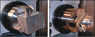
The adaptive balancer compensates for imbalance created by milling a workpiece. This allows the subsequent turning operation to be safer and more productive. The photos on the right show a blank part and a finished part. Machining steps included a series of turning, boring, drilling and milling operations. It was necessary to rebalance the part after each milling operation.
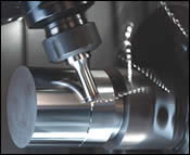
In Nitro-milling, a multi-insert milling cutter becomes a “super tool” for rough-turning an OD. Milling capability on a lathe makes this process possible.
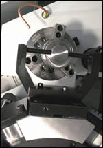
The “water gage” measures part dimensions such as the ID of a bore while the workpiece is still clamped in the machine. This gage uses high-pressure coolant in a manner similar to the way a plug air gage works.
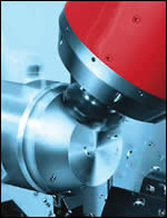
The Spinning Tool rotates as it engages the workpiece in OD turning. Heat and wear are distributed evenly around the cutting edges of the tool.
Abandoning the old method and replacing it with a new and radically different method that hasn’t yet been considered—that is what “disruptive technology” is all about.
In machining, examples of such disruptive technology might include:


- Mounting a button-shaped turning tool in a live toolholder so that the tool spins as it engages the OD of the workpiece rotating in the lathe chuck.
- Aiming fine streams of coolant at the workpiece so that changes in back pressure can measure part size directly in the machine.
- Using a motorized grinding wheel mounted in the tool turret to sharpen a dull cutting tool while it is in the spindle or tool station, or using a similar approach to “dress” the edges of inserts between every cut.
These are some of the developments to come out of the Machining Technology Laboratory (MTL), an R&D initiative dedicated to finding innovations in metalworking processes. Founded in mid-2006 by Mori Seiki, MTL fosters partnerships between the machine tool builder and various tooling manufacturers or other parties. Located at the builder’s facilities in the United States and Japan, MTL enables these partners to systematically explore new concepts made possible by advances in machine tool design. As Greg Hyatt, the chief technical officer at MTL in Rolling Meadows, Illinois, puts it, “Partnering creates the opportunity to find broader innovations than we could working separately in a traditional manner. We can leverage each partner’s special insights in ways not likely to happen otherwise.” Thus, bringing together the expertise of the machine tool builder and the cutting tool manufacturer speeds the development of ancillary technologies that boost machine performance.
According to Mr. Hyatt, MTL was founded with the idea of disruptive technology in mind. This thinking included the almost heretical notion that a good way for a company to go out of business is to listen too closely to what customers say they need. Of course, listening to customers has value, Mr. Hyatt says, but this input leads only to short-term tactical opportunities. “The real benefit in listening to one’s customers is to find out what they didn’t think to ask for,” he says. Those unarticulated needs, the ones too unreasonable to ask for, lead to, in his words, “mission-impossible technology that, when commercialized, has the potential to be so compelling to users that it replaces providers of current solutions.”
After almost a year in operation, MTL has generated a number of developments that are now on the market. More are on the way. In addition, the lab is pursuing whole new lines of thinking about basic machining principles based on its observations of the thermodynamics of the cutting process. This effort may lead to new formulas that will calculate tool life more accurately and help identify opportunities for further productivity gains.
Just as auto makers show concept cars in advance of the commercialization of new technology, MTL shares some of its leading developments here. How “disruptive” these technologies will be is not yet clear. That they appeal to the imagination is already clear.
A Turning Tool That Spins
This technology, developed jointly with Kennametal, takes advantage of live tooling on a multitasking machine tool for turning operations. It is called the Spinning Tool. Mounted in a live-tooling pocket on the tool turret or in the milling spindle of a rotary head, this button-shaped turning tool rotates it engages the OD of a workpiece rotating in the chuck or between centers. Unlike a single-point turning tool, cutting forces are aligned axially rather than radially (see picture on facing page). Thus, cutting forces push primarily against the spindle or the tool turret, which has more mass and rigidity than the inserted toolholder. This makes the cut inherently more stable and resistant to chatter.
Rapidly spinning the tool spreads the heat of the cut around the surface of the insert. Rather than building up on the cutting edge, the heat dissipates. In addition to providing users with the option to perform dry machining, this enables cutting at three times the usual speeds. Tool wear is also spread out. As a result, the company says, metal-removal rates are five times greater and tool life is 20 times longer. Depth-of-cut notching is eliminated, so finer surface finishes are possible in both roughing and finishing cuts. The ability to apply heavy speeds and feeds promotes efficient cutting of tough materials such as nickel-based and other high-temperature alloys.
Rough Turning Gets A Blast Off
The Spinning Tool described above is a good example of how milling capability can be exploited in novel ways to improve turning operations. The integrated mill-turn machine makes these techniques possible. Mill-turn capability also enables a rough turning technique that MTL calls “Nitro-milling.” Nitro-milling results in what researchers consider an explosive increase in roughing productivity.
The photo above shows a milling cutter feeding along the in-line (X) turning axis as the workpiece rotates in the lathe chuck. What makes this process so productive is that the workpiece can rotate in the chuck at speeds fast enough for turning operations. To the milling cutter, the relative motion of the chuck is the same as a very high feedrate in a linear axis. This allows the milling cutter spindle speed (rpm) to be increased substantially without the risk that surface speed will exceed recommendations for the inserts. The result is at least a doubling of metal-removal rates.
In addition to high metal-removal rates, Nitro-milling produces short, broken chips rather than the long, continuous turning chips that can tangle up as a troublesome “bird’s nest.” Tool life also increases. Wear is distributed evenly among all of the inserts in the milling cutter (this effect is similar to an advantage of the Spinning Tool described above). Because no single insert edge is in contact with the workpiece for very long, heat does not build up to excessive and damaging levels. According to Mr. Hyatt, Nitro-milling can result in a fourfold increase in tool life.
There is one more notable benefit to mention. Because the milling cutter and the workpiece rotate in opposite directions, the radial cutting force contributed by the milling spindle can be recovered with a suitable static turning tool. Mounted in the lower turret opposite the milling cutter, the static tool provides bonus productivity because it adds metal-removal capacity but requires no additional power from the spindle drive motors.
Thinking Theoretically
Experiments with the Spinning Tool and Nitro-milling led the MTL to observe some previously overlooked aspects of the thermodynamics at work in machining processes. For example, researchers noted that both tooling concepts involve intermittent contact between the cutting edges and the workpiece. This intermittent contact is possible because milling and turning can be combined in one application. Heat generated by cutting forces can dissipate as the edges move in and out of the cutting zone.
Current formulas for calculating tool life in turning operations assume that contact between the cutting edges and the workpiece is continuous. Now, MTL is working on formulas to account for the effects of intermittent cutting on heat as a key variable. Mr. Hyatt believes that MTL’s research into fundamental machining principles could ultimately represent the lab’s greatest contribution to metalworking science.
Nevertheless, focusing on practical developments that boost machine performance is the main work of MTL. Examples include the following:
Balancing Act
The advantage of an integrated mill-turn machine is the ability to mill and turn a workpiece in one setup. However, milling usually changes the balance of a workpiece. Milling away portions may leave one side or the other with greater mass. As a consequence, rotating this unbalanced part in the chuck for turning operations causes the spindle to vibrate. To prevent excessive vibration from damaging the spindle and cutting tool, the user must slow down the spindle, thereby sacrificing productivity and compromising optimal machining parameters.
An “adaptive balancer” relieves this situation by automatically adjusting for chances in workpiece balance. It allows more stable and vibration-free turning at higher spindle speeds so that more of the mill-turn capability of the machine tool is brought to bear.
In essence, the balancer creates its own imbalance at the point needed to offset the imbalance in the workpiece. The balancer is attached to the chuck and rotates together with the part. As the imbalance in the workpiece changes, the balancer uses two independent, counterweighted rings in its interior to compensate. When the counterweights are positioned at opposite sides (180 degrees from each other), they are naturally balanced during rotation. When the counterweights move away from this neutral position, their angular relationship changes. The force and direction of the resulting imbalance can be set to oppose the force and direction of the balance error in the workpiece, thus “canceling it out.” With less chance of vibration, spindle speed can increase to allow optimal cutting conditions and increased productivity. Reducing vibration also improves surface finish and prolongs tool life.
In addition to compensating for unbalanced workpieces, the balancer can be used to measure the extent of the balance error. Then, material can be selectively removed to balance the workpiece while it is in the machine. This eliminates separate measuring and remachining steps in another setup.
Let’s Call It “Wetrology”
The “water gage” creates a new option for measuring certain critical workpiece features while in the machine. The concept is to utilize high-pressure (1,000 psi) streams of coolant directed at workpiece surfaces. By calculating backflow pressure, the water gage gives a readout of part dimensions such as bore size, OD and taper in much the same way as an air gage.
Like air gaging, water gaging is fast, reliable and accurate. But water gaging has several advantages over air gaging. A water gage can capture measurements in submicron increments and achieve 2-micron repeatability. Coolant pressure blasts away chips and washes the surfaces to be measured. And because the water gage uses the coolant lines already built into spindles, it is flexible and economical.
A water gage can be configured as a plug type for bores and IDs, as a fork for IDs and tapers, and as a ring. Although the gage must be sized and configured to measure a given part feature, the same pressure booster, readout and set of auxiliary electronics work with multiple water gages.
Like any in-process inspection system, water gaging can have an impact on cycle time and machine utilization. However, getting immediate feedback pays off because users can respond faster to issues that might lead to out-of-tolerance conditions. The system also prevents downtime that can occur when results from off-line part inspection are delayed. In some cases, a water gage installed in a subspindle can capture measurements while machining takes place in the main spindle. Thus, measuring on the machine represents no parasitic time.
(Grinding) Wheels Of Fortune
Because Mori Seiki has a tool turret with an integral spindle motor to power live tooling stations, grinding wheels mounted in the turret can provide virtually vibration-free grinding operations, developers say. This makes it possible to do high-precision grinding along with milling and turning. One possibility being explored is renewing the cutting edges of turning inserts without removing the tool from the machine. Another possibility is resharpening the tips of twist drills and other cutting tools inside the machine.
For insert edges, the concept is analogous to redressing a grinding wheel with a diamond tip or roll. Although the grinding wheel is gradually consumed, periodic redressing restores the free-cutting surface and profile accuracy to a like-new condition. MTL expects a similar benefit for turning. For example, “dressing” the insert edge with a grinding cycle allows the insert to hold a wiper geometry and edge prep capable of producing part size and finish comparable to a grinder. Typically, normal wear of the insert prevents turning operations from achieving these results on a consistent and sustained basis. Dressing the insert would reverse that limitation. According to Mr. Hyatt, the grinding cycle would remove only a few microns and be timed with every tool change or before critical finishing cuts. Thus, one insert could maintain constant surface finishes throughout its life.
A system whereby cutting tools could be renewed or resharpened automatically without being removed from the machine has huge implications for unattended machining, Mr. Hyatt says. It is conceivable that a machine tool could run continuously without operator intervention for weeks and weeks.
To Market, To Market
Mr. Hyatt stresses that the success of MTL will be judged by the acceptance of its developments in the marketplace. For this reason, commercialization has been part of basic project planning. The adaptive balancer and water gage are currently market-ready, with the spinning tool close behind. Where appropriate, patent protection for these developments has been secured or applied for. New technology from the lab will be available through licenses granted as part of machine tool purchase agreements.
This commitment to commercialization goes back to the concept of disruptive technology, which was part of the original inspiration for starting MTL. Potential users of integrated milling and turning centers, multitasking lathes with multiple spindles and tool turrets, and other advanced machine tool designs can be put off by their complexity and unfamiliarity. This wariness can be overcome by the compelling value that these machines represent as productivity resources. MTL seeks to leverage the flexibility and capability of these machines with innovative cutting tool concepts in order to enhance the value of these machines to users.
This is sure to promote wider acceptance of these machines. Where the lab’s developments exploit unique capabilities of the company’s own machine tool designs, all the better for this builder. As Mr. Hyatt points out, Mori Seiki wants to see its machine be the ones that are displacing existing technology. “We’re all in favor of that kind of disruption!” he says.


Related Content

Selecting a Thread Mill That Matches Your Needs
Threading tools with the flexibility to thread a broad variety of holes provide the agility many shops need to stay competitive. They may be the only solution for many difficult materials.
Read More
Best Practices: Machining Difficult Materials
Cutting hardened steel, titanium and other difficult materials requires picking the right tools, eliminating spindle runout and relying on best practices to achieve tight part tolerances.
Read More
New Modular Tool Options for Small Spindle Milling
Tooling options have been limited for small spindle milling applications. Now modular, indexable systems are available that provide broad flexibility to get the right cutter for the job with less inventory and at lower cost.
Read More
Buying a Lathe: The Basics
Lathes represent some of the oldest machining technology, but it’s still helpful to remember the basics when considering the purchase of a new turning machine.
Read MoreRead Next

The Cut Scene: The Finer Details of Large-Format Machining
Small details and features can have an outsized impact on large parts, such as Barbco’s collapsible utility drill head.
Read More

3 Mistakes That Cause CNC Programs to Fail
Despite enhancements to manufacturing technology, there are still issues today that can cause programs to fail. These failures can cause lost time, scrapped parts, damaged machines and even injured operators.
Read More