

According to RobbJack, the Mirror Edge feature helps stabilize the end mill’s contact with the workpiece surface to synchronize the vibration of the cutting tool and the workpiece.
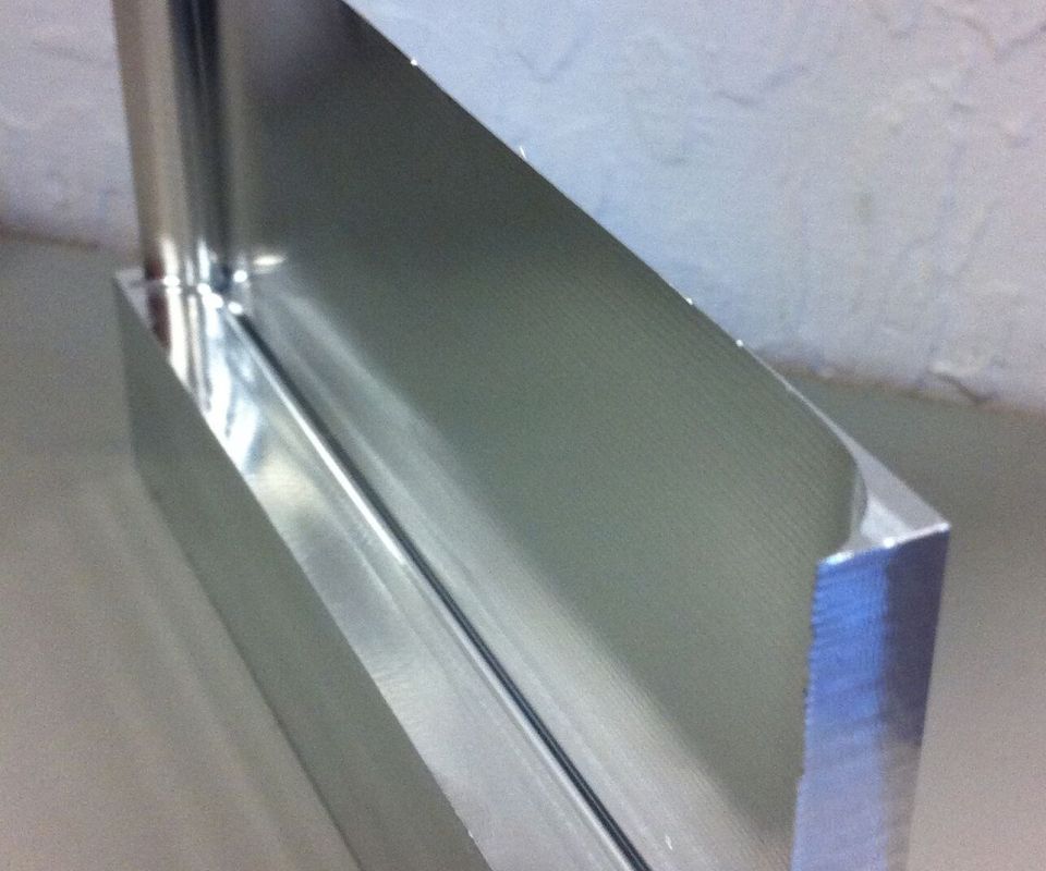
The ability to cut thin walls that are straight, smooth and accurate is one of the benefits of using an end mill that damps vibration effectively.

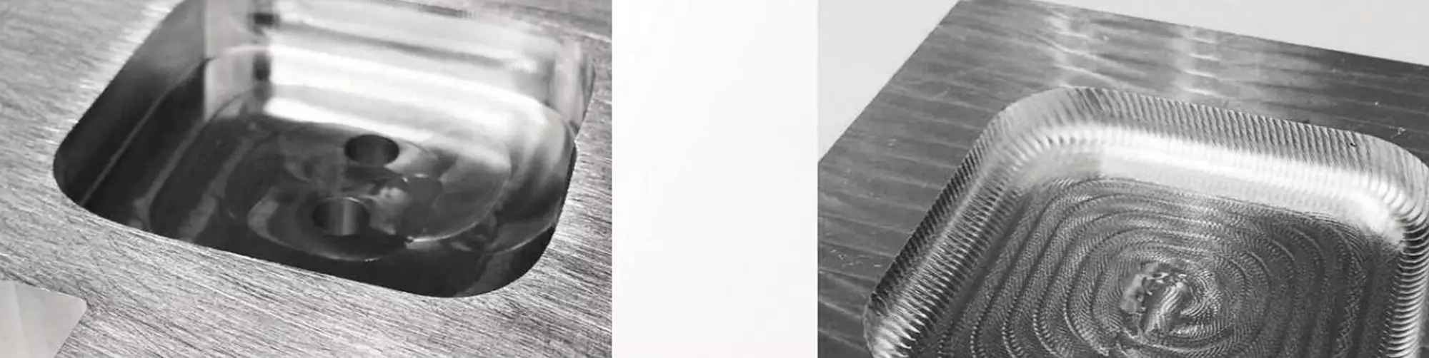
This photo and the next compare a pocket showing the effects of uncontrolled chatter (next photo) with a pocket machined with an end mill that controls chatter with the Mirror Edge feature.
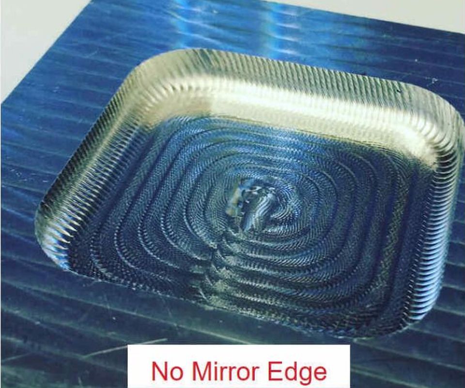
This pocket shows the effects of uncontrolled chatter.


In a machining process, vibration causes chatter. More specifically, chatter occurs when the workpiece and the cutting tool are vibrating at different frequencies. Literally, the workpiece is moving in one direction while the cutting tool is moving in the other direction. Of course, these relative motions are slight and happen at many times a second. Chatter is the resultant sound of the workpiece and the cutting tool knocking into one another at a high rate. This knocking does more than make an irritating noise: It also damages the tool, degrades the workpiece surface, harms the spindle and may leave part features out of tolerance.
Cutting tool manufacturer RobbJack has a strategy for dealing with chatter that is based on the concept of getting the cutting tool and the workpiece to vibrate in the same direction at the same rate. To this end, the company has developed an end mill design (primarily for milling aluminum at high feed rates) that gets the cutter and the workpiece to synchronize the frequency of vibrations during machining. This does not stop the vibration, but rather stops the knocking caused by out-of-sync vibrations. Apparently, when the knocking goes away, so do the other unwanted side effects.


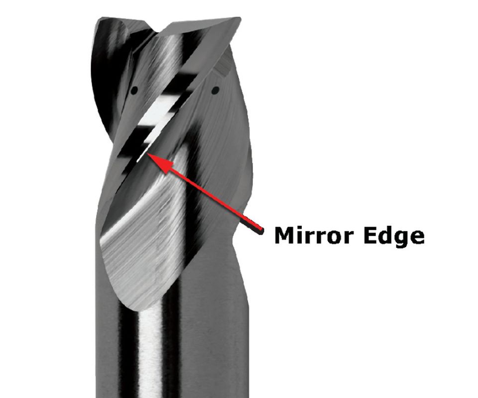
Mike MacArthur, vice president of engineering at RobbJack, explains that the end mill design includes a special edge preparation that creates an additional surface along the trailing side of each spiraled flute. The company calls this additional feature the Mirror Edge, because it is highly polished and shiny. This added edge is 0.001- to 0.002-inch wide, so it can barely be discerned by holding the tool and slightly turning it in the light. The first photo in the slideshow above captures the slender band of light reflected by this edge as indicated by the arrow. The other reflections alongside it are, respectively, the land and the cutting edge of the flute normally found on a spiraled end mill.
Mr. MacArthur says this added edge is just enough to keep the flute in contact with the workpiece until the next flute is engaged (the end mill has three tightly spiraled flutes for this reason). This highly polished edge minimizes frictional rubbing, so it creates virtually no heat and does not alter the workpiece surface. The constant contact prevents both the tool and the workpiece from “going their separate ways” in response to various forces inducing vibration. Thus, the tool and workpiece keep moving in unison to maintain synchronization regardless of the frequency of the vibration. Neither the tool nor the workpiece can “bounce away” from the other and fall into a different rate (frequency) of vibration, Mr. MacArthur says.
This out-of-sync condition can occur instantly, and once it starts, the tool and workpiece begin bouncing off one another more forcefully with each passing of the flutes across the workpiece. This worsening condition is detectable as chatter. “A machinist can hear the rise and fall in the sound of this chatter as the frequencies go in and out of phase,” he says.
Keeping vibration in sync to avoid negative consequences does impose certain requirements on the machining process. According to Mr. MacArthur, the tool must be used with flood or through-tool coolant to keep chips from interfering with the action of the Mirror Edge. The tool works best in aluminum, because the high spindle speeds used for cutting this material tend to create higher cutting frequencies than those encountered at lower spindle speeds when machining harder materials such as steel or titanium. (However, Mr. MacArthur notes that the Mirror Edge can be added to end mills customized for specific applications in these materials, although other vibration-control techniques are likely to be needed for full effectiveness in these cases.) End mills with Mirror Edge can be used at the machine tool’s highest spindle speed in aluminum without any chatter. This enables the feed rate and metal removal rate to increase substantially. Stepovers that are 50 percent of the tool radius are recommended, along with chip loads equal to the tool diameter times 0.016-inch per flute.
Mr. MacArthur says that applications with deep pockets and/or thin walls are the most suitable for these end mills, however, certain programming techniques are in order for machining thin walls. For example, each Z level of a pocket should be roughed and finished before proceeding to the next, lower Z level. Sufficient stock should be left on the walls for the finishing pass to maintain rigidity. This stock helps support the wall ahead of the cut. Applying constant-chip-load pocketing routines in the CAM program is also recommended. He says walls as thin as 0.005 inch and as tall as 3 inches can be produced effectively in this manner. The resulting wall will be straight and smooth.
Perhaps a more significant benefit is the substantial increase in metal removal rates that Mr. MacArthur reports for these end mills in aluminum. “A fivefold increase in metal removal rates compared to traditional end mills is possible,” he says. “Removing as much is 42 cubic inches of material per minute can be attained with significant increases in tool life to boot,” he adds, noting that walls thinner than 0.020 inch limit removal rates to accommodate the smaller stepdowns in Z that are required.
Currently, the Mirror Edge preparation is available on RobbJack’s A1-303 and FM series aluminum end mills in diameters from 1/8 to 1 inch on standard tools, and on tools as small as 0.010 inch in diameter on special order.


Related Content

Toolpath Improves Chip Management for Swiss-Type Lathes
This simple change to a Swiss-type turning machine’s toolpath can dramatically improve its ability to manage chips.
Read More
Choosing Your Carbide Grade: A Guide
Without an international standard for designating carbide grades or application ranges, users must rely on relative judgments and background knowledge for success.
Read More
A New Milling 101: Milling Forces and Formulas
The forces involved in the milling process can be quantified, thus allowing mathematical tools to predict and control these forces. Formulas for calculating these forces accurately make it possible to optimize the quality of milling operations.
Read More
Threading On A Lathe
The right choices in tooling and technique can optimize the thread turning process.
Read MoreRead Next

Ten Questions About Chatter
If you want to use a high speed milling spindle to machine aggressively, then information about chatter should be more than just background noise. Here are some basics.
Read More
The Cut Scene: The Finer Details of Large-Format Machining
Small details and features can have an outsized impact on large parts, such as Barbco’s collapsible utility drill head.
Read More
3 Mistakes That Cause CNC Programs to Fail
Despite enhancements to manufacturing technology, there are still issues today that can cause programs to fail. These failures can cause lost time, scrapped parts, damaged machines and even injured operators.
Read More