
Getting To Know Knowledge-Based Machining
The term refers to different levels of automation that CAM software developers are building into their NC programming software.


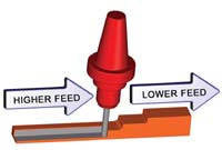
Feed rate optimization provides efficient, varied feed rates tailored to each job, using values reflecting the actual performance characteristics of the machine tool.
Part geometry must be related to machinable features, and these features, in turn, must be related to operations performed on a machine tool. Knowledge-based machining helps standardize and automate this process.
Capturing knowledge about the best way to machine a feature allows this expertise to be applied to similar situations, making shopfloor operations more consistent and more reliable.
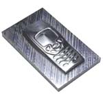
Fully automated programming systems enable non-expert users to create tool paths for CNC machining. This mobile phone model was programmed in 6 minutes with PowerMill AutoCAM, its developers say.
Knowledge-based machining is evolving into a form of process planning, whereby cutting operations can be managed and organized in a streamlined fashion.
Hole processing involves many repetitious steps that lend themselves to automated programming with templates. Advanced systems give users option for optimizing the efficiency and accuracy of the holemaking process.
Who knows the best way to drill a 0.5-inch hole in a 2-inch thick plate of D2 tool steel? Who knows the most efficient pocketing routine for milling a cavity in 7075 aluminum with a 1-inch end mill? Who knows your shop's favorite roughing tool for its newest 15-hp, 40-taper vertical machining center? Who knows what thread milling tools are stocked in your shop's tool crib and when to use them?
Answers to these questions are important. The answers may determine whether or not an application is successful or if a job makes money. The knowledge called for in questions such as these may be general, reflecting the best practices currently followed by industry, or the knowledge may reflect the experiences and preferences that accumulate in a shop, given its unique collection of machine tools, cutters, workholding fixtures and so on.


All of this knowledge is necessary to do effective machining on CNC equipment. Not knowing the right speeds and feeds for an operation in a certain workpiece, for example, may lead to hazardous conditions on the shop floor or to inefficient, money-wasting processes. Likewise, not knowing that a shop routinely uses thread milling instead of tapping for holes more than 0.5 inch in diameter on its horizontal machining centers is to miss an opportunity for optimizing and standardizing that operation.
CAM software developers have been introducing new programming features to make this essential knowledge part of the automation built into their systems. This automation helps streamline the process of generating NC programs tailored for optimal machining. "Knowledge-based machining" is a term often applied to these features. However, knowledge-based machining has no standard definition or precise meaning. The term refers to a wide range of capabilities varying from system to system.
There are several ways to characterize the various approaches to knowledge-based machining. Some systems emphasize providing knowledge about machining while other systems emphasize capturing knowledge about machining. Most systems offer a mixture of these two approaches. Likewise, some systems tend to organize knowledge around machining processes whereas other systems tend to organize knowledge around workpiece conditions. Here again, most systems are not strictly one way or the other.
Even looking at a few CAM systems reveals the range of knowledge-based machining functions currently available. Many other variations and innovations can be found in systems not mentioned here.
The most important point to keep in mind is that knowledge-based machining represents a broad effort among CAM developers to make CNC programmers more productive and more consistent and to make CNC operations more efficient and more reliable.
Workpiece Features
One of the common concepts found in knowledge-based machining is linking features with machining steps. Features are portions of part geometry that a specific set of machining routines can produce. Holes, pockets, slots and bosses are examples of machined features. Knowledge about how these features are to be machined can be stored in a database. This knowledge may include the sequence of steps required to produce the particular part feature as well as the appropriate machining parameters for each step (speeds and feeds based on workpiece material and cutting tool type, for example).
Part geometry is always the starting point for CNC programming. Part geometry is either created by the user from a print using CAD tools within the CAM system or is imported from an outside source such as another CAD/CAM system. Part features as represented in this geometry must be identified correctly and linked to machining operations that produce them on a machine tool.
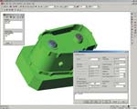
The fundamental principle of using features as a link to machining knowledge can be seen in the FeatureCAM family of CAM packages from Engineering Geometry Systems (Salt Lake City, Utah). This software takes an unusual approach to creating part geometry. Part geometry is created as a group of features, with dimensional data and other attributes added by the user in response to prompts from the system. This approach contrasts with the more conventional method of selecting points, lines and arcs to create part geometry.
In FeatureCAM, the user defines the geometry (the size and dimensions of the feature) either by using the system's CAD tools or by typing in the dimensions. Once the user indicates that the part being created has a pocket or a hole or other feature, the system asks questions and offers choices to solicit all of the information necessary to produce the geometry as well as to automate remaining programming steps. For example, with a rectangular pocket, the user either creates a rectangle using the CAD tools or enters the dimensions and position of the pocket. Then the program asks if the user wants to add different components to the pocket, such as a chamfer or bottom radius. When selected, the program automatically adds those components to the feature.
The program then determines roughing and finishing operations for each feature, selects tools for each operation, calculates feeds and speeds, generates tool paths and generates postprocessed NC code. Also, even with the automation of knowledge-based machining, FeatureCAM allows users to edit the program. The automation is controlled by a set of machining attributes that can be modified to achieve different machining strategies.
When a CAD file is imported to provide part geometry (the software supports widely used exchange formats as well as accepts a variety of native formats), the software automatically recognizes geometry that corresponds with the features used for part creation. Optional in FeatureMILL2.5D and standard in FeatureMILL3D, automatic feature recognition allows such part features as holes, pockets and milled slots to be linked to machining steps following the manner in which a part constructed of features is programmed automatically.
In the 3D package, the part model is analyzed for contoured shapes that are not recognizable as simpler features. The surfaces of these contoured shapes are used as the basis for roughing and finishing strategies following a variety of machining techniques that the user selects. These techniques include plunge roughing, spiral finishing, steep slope remachining and Z-level semi-finish, to name a few.
Knowledge Capture
Providing speed/feed tables, tooling libraries, and other machining data is one level of knowledge-based machining. Capturing knowledge about machining is another strong trend in knowledge-based machining systems. GibbsCAM from Gibbs and Associates (Moorpark, California) makes an interesting study because different levels of "knowledge capture" are built into this software.
The machining databases provided in the software are the first level. The company says the Cutdata database option has more than 70,000 discrete entries in these databases to match the cutting tool, workpiece material, type of cut, depth of cut, and so on, with speeds, feeds, stopovers and other values. These machining databases are readily modified and enlarged by the user, allowing this aspect of GibbsCAM knowledge-based machining to capture knowledge of a shop's practices and experiences.
The real emphasis on knowledge capture emerges on two further levels, however. On the next level, the software allows the user to create templates of multi-process part programs. In fact, this GibbsCAM function is called Multiple Process Programming. For example, all of the details for producing a certain type of hole (pilot drill, drill, ream, counterbore, chamfer plus specifications for each tool required and associated machining parameters) become a template. This template, stored in a library, can be recalled whenever that type of hole is encountered in another similar workpiece.
The same sequence of steps and the same parameters can be incorporated into a new part program, or the sequence and parameters can be modified. Additional templates can be applied where appropriate; it's possible to create a complete program from templates.
Bill Gibbs, CEO, makes a clear distinction about the intent of these templates and other approaches to knowledge-based machining. "This is not an attempt to tell the machinist how to machine a part. Rather, it's a way to preserve the machinist's know-how so it can be implemented in similar situations," he says. These templates automate the re-use of knowledge without re-entering a lot of data, so they do represent a significant streamlining of the programming process. Nevertheless, Mr. Gibbs resists calling this automated programming. In his view, excessive reliance on automated systems tempts a shop to settle for techniques that level it with its competition. "Software ought to leverage a shop's knowledge and experience, not dilute them," he says. Multiple Process Planning templates allow a shop to store best practices and use them where appropriate, thus supporting standardization while also protecting the shop's expertise.
A step beyond templates takes the user to a level on which the system is given decision-making power. These decisions are based on "rules" created by the user to reflect preferred techniques. By following these rules, the system automatically selects a sequence of machining steps. It picks the cutting tools, speeds and feeds and so on. It makes calculations and applies them. For example, it sets stepovers as a percentage of cutter diameter as set by the user and applies offsets for a roughing pass to leave uniform stock for finishing—also set by the user.
GibbsCAM uses a Wizard approach, similar to the task wizards popularized by Microsoft Windows, to capture a shop's knowledge and how it prefers to perform various operations. The Wizard approach presents an easy-to-follow user interface dialog that hides a relatively complex knowledge base and decision matrix. Developers can create wizards for very simple or very complex logic. In this case, the Wizards in GibbsCAM help the user through the process of establishing rules and then applying the rules when the situation arises in programming session.
When initially setting up the Wizard, the user is presented with choices and options that the Wizard needs to know in order to apply the appropriate rule. It may ask for certain numerical values to be entered. This input allows the Wizard to make decisions about how to machine the feature in question. These decisions are "intelligent" in that they reflect the shop's own logic, rather than the logic predetermined by the software developer. Once encoded, the underlying logic of the Wizard will base its decisions upon these values. However, values returned by the Wizard are only suggestions and can be overridden by the user at any time.
Currently, the latest version of GibbsCAM offers a range of Wizards, from a simple stock definition Wizard to an extremely complex Wizard, to assist in defining compound hole-making processes. According to Bill Gibbs, the Wizard approach sticks to the philosophy embodied throughout the company's software products: Software features must be easy to learn, simple to apply and fast with results. Otherwise, despite the value of the feature's function, the feature is not likely to be used to full advantage.
Knowledge Of The Future
An interesting outlook on knowledge-based machining comes from the developers of Esprit, the CAM software from DP Technology (Camarillo, California). This company sees knowledge-based machining not only playing a key role in further automating the programming function, but also enabling the shop floor to implement innovative concepts such as STEP-NC.
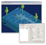
In this approach, knowledge-based machining has its greatest value in organizing, managing and re-applying machining steps for complex workpieces—parts with many features, parts that are rotated or indexed to reach several sides, parts requiring many different operations, and so on. Thus, knowledge-based machining is evolving into a form of high-level process planning. Process planning, in this context, summarizes all of the operations that must be performed to machine the complete part. The collected details about machining each part feature form a "work plan," which consists of the machining cycles, cutting tools, and cutting strategies to be used for creating the tool path.
To sort out what features are being cut, how they are being cut, and which cutting tools are being used, Esprit's knowledge-based machining Project Manager creates a "feature tree." This feature tree shows how the workpiece is divided into machinable features such as holes, slots and pockets. Under each feature is a sub-list of cutting operations that will be performed to machine this feature. For each operation on this sublist, another list is given showing what tools have been selected from the tooling library.
Following the branches on this tree allows the user to review, change or rearrange the work plan for machining the part. Work plans can be saved and modified later to produce new work plans for similar workpieces. Machining cycles can also be combined together as a standard process for a feature. For example, a standard process for machining a pocket might include steps such as:
- Rough the pocket with a concentric climb cut,
- Change the tool,
- Finish cut the walls using a contouring cycle and
- Finish cut the bottom of the pocket with a zig-zag pocket cycle.
This standard process is saved in the Process Manager database to be applied as a template to similar features on other parts.
When a work plan is completed, the programmer pushes the button to generate corresponding tool paths in G codes. Looking ahead, planners at DP Technology see this work plan being created as a part of the design and engineering effort to produce a digital product model in a standardized, exchangeable format called STEP-NC. In concept, STEP-NC calls for the final step of generating G code tool paths to be held off until the workpiece corresponding to the product model is about to be machined on a piece of CNC equipment.
Software in the machine tool's CNC unit would apply the power of knowledge-based machining on the shop floor. According to DP Technology's Chuck Matthews, VP marketing at DP Technology, this new scenario on the shop floor makes an effective knowledge base critical. "While a work plan contains higher level, more detailed information, it requires effective KB software to simplify the editing process. A CAM system with such a knowledge base has the capability to edit the work plan easily, minimize errors by enforcing rules, and capture changes to improve process planning in the future."
Mr. Matthews also comments on the future of knowledge-based machining. "In the past, the up-front investment required of users to build a knowledge base was high. In the future, more effective database management tools will allow CAM developers to store the choices and decisions that a CNC programmer makes and automatically construct the rules and preferences implied by the CNC programmer's thinking."
This emerging generation of knowledge-based machining will significantly enhance the programmer's productivity at the same time it promotes the most effective use of shopfloor resources, predicts Mr. Matthews. He says that a version of this new capability is now under development as the KnowledgeBase Engine for the next release of Esprit software, which is to be released early next year.
Continuous Improvement
Knowledge-based machining, whatever form it takes, assumes that knowledge changes and grows. As programmers store shop-proven processes and customize databases, the benefits are realized throughout the shop. Operations become more consistent and uniformly superior to past experience. Knowledge-based machining facilitates continuous process improvement; in other words, a shop gets better and better at what it does. For every shop, this is a never-ending pursuit.


Related Content

When to Use Custom Macros With a CAM System
Custom macros can offer benefits even when using a CAM system to prepare programs – but must be implemented with the right considerations.
Read More
CAD/CAM System Requirements: An Overview
CAD/CAM programs are among the most demanding kinds of computer software. Smooth operation requires careful consideration of computer specifications.
Read More
Large-Format Machining With Small Cutting Tools and Dynamic Motion
Napoleon Machine, a defense contractor that provides parts for the M1 Abrams tank, recently took advantage of a CAM feature that allowed the company to streamline its cutting strategies and program offline. Here’s how the shop cut cycle times nearly in half with its large-format five-axis machining operations.
Read More
How Integrated CAD/CAM Transforms Inventions Into Products
The close connection between CAD and CAM is what links creative ideas to practical production for this unique custom manufacturer.
Read MoreRead Next


The Cut Scene: The Finer Details of Large-Format Machining
Small details and features can have an outsized impact on large parts, such as Barbco’s collapsible utility drill head.
Read More
3 Mistakes That Cause CNC Programs to Fail
Despite enhancements to manufacturing technology, there are still issues today that can cause programs to fail. These failures can cause lost time, scrapped parts, damaged machines and even injured operators.
Read More