
Hard Milling By The Numbers
Here are some speeds, feed rates and depths of cut for a productive hard milling process.
.jpg;width=70;height=70;mode=crop;format=webp)
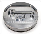


Figure 2

Figure 1
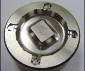
The forging die (top) was machined out of 42-HRC material with tools ranging from a 12-mm ballnose end mill run at 6,000 rpm and 236 ipm, to a 3-mm ballnose tool run at 32,000 rpm and 63 ipm. This smaller tool, a finishing tool, used a radial depth of cut of 0.0039 inch. The die cast die (bottom) was machined from 60-HRC material using tools ranging from a 3-mm ballnose tool run at 19,000 rpm and 133 ipm, to a 0.2-mm ballnose tool run at 40,000 rpm and 16 ipm. This small tool took a 0.000118-inch radial depth of cut.


The problem with switching to a new and different method of machining is that your old and established expectations may not help you anymore.
Many shops have implemented hard milling through high speed machining as a way to generate intricate die and mold forms on the machining center, with less need for EDM and hand finishing. However, machining hard steel with small tools taking fast, light cuts is not the way many shops are accustomed to machining these parts. For the shop without this hard milling experience, just how fast is the cut? How light are the light passes? Assuming the shop has a machine tool and cutting tool appropriate for this process, how does the shop find the cutting parameters that will efficiently generate the smooth surfaces and precise details in hard steel?


William G. Howard Jr., vertical machining center product line manager for Makino, wrote a book on hard milling—“High-Speed, Hard Milling Solutions” from Hanser Gardner Publications. He also detailed the process of hard milling at a recent technology expo, which took place at Makino’s die/mold headquarters in Auburn Hills, Michigan. Among the tips he offered were some rules of thumb for finding the right machining parameters for hard milling.
These parameters are not the whole process (hence the need for the book). In addition, the cutting tool manufacturer may be able to offer more productive and specific parameters than these, he says. However, if the shop does have a higher-performance machine with higher-performance tooling, and in the absence of experimentation or expert advice to offer more specific parameters, the ranges and equations presented below should give the shop a good starting point for applying hard milling effectively.
Speed
How fast to cut in the hard milling process depends on just how much hardness is involved. Use these ranges as starting points:
| Workpiece Cutting | Hardness Speed Range |
| Up to 45 HRC | 600 to 1,000 sfm |
| 45-58 HRC | 400 to 600 sfm |
| 60+ HRC | 200 to 400 sfm |
Of course, the spindle speed in revolutions per minute that equates to this value in “sfm” (surface feet per minute) will be determined by the diameter of the tool. Because the tool is likely to be small, a fast spindle may be needed to realize this cutting speed range.
The use of a ballnose end mill for hard milling of complex die and mold surfaces only makes the need for high speed more likely. When a ballnose tool cuts at light axial depths of cut, the tool does not cut on its full diameter. To determine the rpm value necessary to realize the needed sfm value with such a tool, use the tool’s effective diameter, which is calculated with the formula in Figure 1.
Feed Rate
The chip load, or feed rate in inch per tooth, can be approximated as a function of the actual diameter of the tool. For the starting point for a hard milling feed rate, use these ranges:
| Workpiece Hardness |
IPT Feed Rate |
| Up to 45 HRC | 3 to 4 percent of tool diameter |
| 45-58 HRC | 2 to 3 percent of tool diameter |
| 60+ HRC | 1 to 2 percent of tool diameter |
These feed rates assume a standard tool length. If an extended-length tool is needed because the hard-milled feature is also hard to reach, then a lighter feed rate is likely to be warranted.
Depth Of Cut
The “step-over” and “step-down” depths of cut are similarly dependent on the hardness of the material—to a point. A more significant factor affecting step-over (or radial depth of cut) may be the desired surface finish of the part.
These are the maximum depths of cut that should be employed in a hard-milling process:
| Workpiece Hardness | Depths Of Cut |
| Up to 45 HRC | Radial: 50 percent of tool diameter Axial: 10 percent of tool diameter |
| 45-58 HRC | Radial: 45 percent of tool diameter Axial: 7 percent of tool diameter |
| 60+ HRC | Radial: 45 percent of tool diameter Axial: 5 percent of tool diameter |
These maximum values preserve the life of the tool. However, when the aim of hard milling is also the smoothness of the surface, an even lighter radial depth may be needed.
The surface finish requirement itself can be used to calculate this lighter step-over value. That’s because the surface finish value is an indication of the cusp height between passes, and the cusp height between adjacent passes with a ballnose tool can be mathematically determined from the radius of the ball.
The formula relating the radial depth of cut to surface finish using a ballnose tool is shown in Figure 2.
The cosine term reflects the possibility of machining draft angles or tapered or sloped surfaces. “A” is the average angle of engagement between the tool and the angled surface. For example, if a 0.25-inch-diameter tool (0.125-inch radius) was used to achieve an RMS surface finish of 40 microinches at an average angle of engagement of 45 degrees, then the step-over would be calculated taking the square root of 8 × 0.125 × 0.00004, multiplied by the cosine of 45 degrees. This works out to 0.0044 inch, or about 1.8 percent of tool diameter. Use this equation to determine how small the radial depth of cut may need to be to meet a demanding surface-finish requirement.
Feed rate affects surface finish as well. The pass of each cutting edge as the tool advances creates a “cusp” of its own. Therefore, if a smooth surface is the goal, then the same value calculated as the limit of the radial depth should also be applied as the upper limit on the inch-per-tooth feed rate of the tool.


Read Next


3 Mistakes That Cause CNC Programs to Fail
Despite enhancements to manufacturing technology, there are still issues today that can cause programs to fail. These failures can cause lost time, scrapped parts, damaged machines and even injured operators.
Read More
The Cut Scene: The Finer Details of Large-Format Machining
Small details and features can have an outsized impact on large parts, such as Barbco’s collapsible utility drill head.
Read More