Helpful Alignment Tips for Machine Shops
This whitepaper from Pinpoint Laser Systems is designed to assist machine shops in aligning critical shop equipment.


Background
Rotating machinery works best, runs more efficiently, and produces better quality parts if it is properly aligned. Frequently, we hear from customers that are voicing concerns about lathes where the chuck or collet is not in alignment with the tailstock or the tool holder and the cut parts are tapered. Sometimes, the tool moves in an axis that is no longer parallel with the centerline of the chuck that is holding the rotating workpiece. Often, operators just suspect an alignment problem with a boring mill or a lathe or a spindle machine but measuring the error takes too long so they just “hope for the best.”
Proper alignment of spindle equipment is easy to perform and improves manufacturing efficiency and profits. The following application note describes how to use a Pinpoint Laser Microgage system to quickly and precisely evaluate the alignment of your spindle system. This information can then be easily applied to re-aligning the machine itself or applying correction factors for future production runs.


In most cases, lathe and spindle misalignments fall into two categories; offset or centerline misalignment and parallelism or angular misalignment.
Offset or Centerline Misalignment
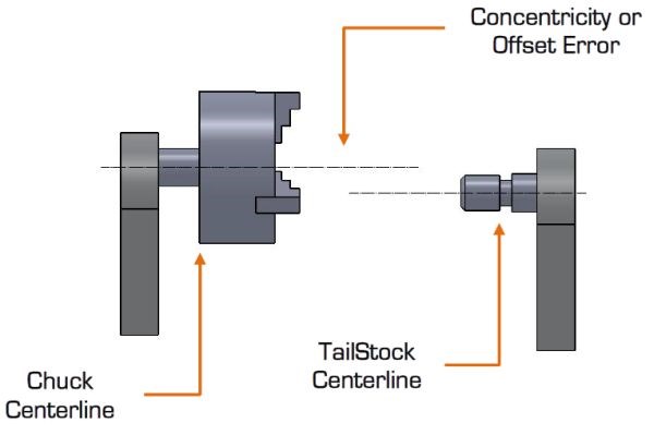
Offset or concentricity misalignments occur when the centerlines of the rotating spindle, chuck, tool holder or work piece holder are displaced from each other. Offset mis-alignments fall into 2 axes, typically referred to as vertical or horizontal. These centerline or offset errors tend to be fixed and maintain a constant error value as you travel further away from the chuck or tailstock.
Parallelism or Angular Misalignment
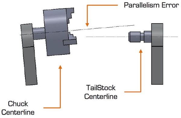
Parallelism misalignment occurs when the axes of rotation and the axes of tool movement are not parallel to each other. These errors can typically be quantified by an angular error value or a displacement error over a specific distance. The key attribute with angular errors is that they grow with distance, so the further you move from the source (chuck or spindle), the greater the angular error becomes. Often, a machine tool will exhibit both of these misalignment errors requiring additional measuring and alignment procedures or machine tool compensation.
Pinpoint builds a variety of laser alignment systems for different applications and machinery configurations. These systems provide better measuring accuracy and are easier to use than many conventional alignment devices or methods. This note and the equipment described within are primarily for aligning spindle machinery that is anywhere from 24 inches to 80 feet in length. The equipment is well suited for checking the concentricity / offset and parallelism alignment between tools, work pieces and the machine elements that support them.
This application note will give you a step-by-step procedure on what equipment is needed, how it should be set-up, and the steps for taking readings, along with a simple procedure for downloading your readings and computing the alignment characteristics of your machinery. If you have any questions or ideas about other alignment procedures, please call us and ask for our Engineering Support team at 800-757-5383.
Alignment Equipment Needed
- Microgage 2D Alignment System with Cylindrical Laser;
- Microgage Receiver Cylindrical Mount;
- Marking Tape or Marker;
- Tape Measure;
- Notebook & Pencil;
- Microgage DCU & Pinpoint Capture software (optional);
- Laptop or PC for data storage & computations (optional).
In addition to these basic items, you will need a collet or fixture that can hold both the laser and receiver cylindrical mount securely in-place.
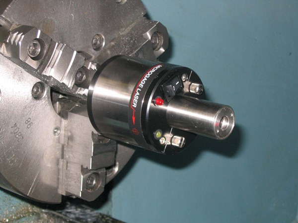
How it Works
The self-contained, cylindrical Microgage laser is placed into the machine chuck, spindle or another rotating part of the machine. This laser projects a narrow beam that extends the centerline of the chuck or spindle down the length of the machine. A Microgage receiver is secured into an opposing spindle, attached to a moving tool holder, or similar machine element and collects the laser light. As the chuck is turned and/or the tool holder or opposing spindle moved the relative position of the laser beam to the Microgage receiver will move if misalignments are present. The receiver is connected to a Microgage display and precise readings are given as parts of the machine are turned and moved. Readings are recorded manually or with a laptop and Pinpoint’s Capture software and calculations can be made to determine runout, concentricity errors, offsets, parallelism errors and other valuable information to diagnose machines and bring them back into alignment.
Measuring Procedure
First, the Microgage Cylindrical Laser is placed into the chuck, and spindle or a collet mount so that the laser beam can project along the axis of rotation. It is important to note that the laser beam will not be perfectly centered or parallel to the axis of rotation and may appear to be off the center of the tailstock centerline – this is normal.
The Microgage Laser typically has a 2 to 3 inch long mounting shank, of a precise cylindrical dimension, that is held in the chuck. The laser beam then travels some distance down the length of the machine before it reaches the Microgage Receiver. If the chuck does not grip the laser shank evenly or if there is any reason that the laser doesn’t sit squarely in its mounting position the errors will be exaggerated over the run of the laser beam. For example, if a piece of debris such as a metal chip acts like a shim and the back end of the laser shank is moved off center by 0.005 inch the laser beam will be deflected off the rotational centerline. So, a 0.005” deflection acting over a 3 inch shank would translate to a 0.100 inch beam deflection at a laser distance of 60 inches (0.005” / 3” = 0.100” / 60”).
Considering the example above, if the chuck or spindle holding the laser is manually rotated the laser beam at 60 inches will produce a circular path that has a radius of 0.100 inch or a diameter of 0.200 inch. Not to worry, our alignment procedure compensates for this.
Next, the Microgage receiver is secured into the Microgage 2D Bore Mount which places the dual axis receiver along the centerline of the shank or mounting surface (taper, locating hole, pin, etc.). The mount and receiver are then attached to the tail stock, tool holder or any other part of the machine tool that you are trying to check relative to the centerline of the chuck.
Here again, it is important to note that the laser beam is unlikely to hit the exact center of the Microgage Receiver target. The stack up of moving parts, the elements of a machine tool and even parts of the measuring system contribute to this initial position of the laser beam on the receiver. At this point you are ready to turn on the Microgage Display, if you have not already done so, and start recording your readings for alignment.
Making the Measurements
Early in this application note we outlined two types of alignment error; offset and angular. The chuck or spindle is likely to have a little of each. The position and orientation of the tail stock may also contribute to an offset as well as an angular error. By taking a number of measurements with the Microgage Laser and Receiver in various rotational positions we are able to measure the combined offset and angular errors. Offset errors remain constant over the length of the machine while angular parallelism errors increase with distance down the length of the machine. Then by moving the receiver to a new location and repeating the measurements we can determine the individual angular error.
Start by manually turning the chuck or spindle to a starting or “home” position and where the “A” on the laser housing is facing upwards.. Now, turn the chuck precisely ½ turn (180 degrees) until the “D” on the laser housing is facing upwards – these two points are your rotational positions for taking measurements at the chuck. During the measurement run you do not want to move the laser in the chuck because this will disrupt your readings and alignment measurements.
Similarly, the receiver is rotated through a precise1/2 turn for two measurement locations. We recommend label up and label down. You are now ready to start recording your measurements.
The chart below shows the orientation of the laser transmitter and the receiver for each measurement. Move one element (chuck position or receiver) at a time and take your measurement. For each position you want to record both the vertical (Vert.) and the horizontal (Horz.) values being careful to note the sign of the measurement; either + or -.
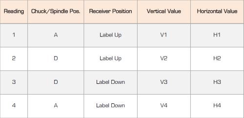
These 8 recorded values can now be used to calculate the total error or misalignment between the spindle or chuck supporting the laser and the mounting point for the receiver.
Using the formula below you can determine the vertical centerline position;
[((V1 + V2) / 2) + ((V3 + V4) / 2))] / 2 = Vertical Centerline
[((H1 + H2) / 2) + ((H3 + H4) / 2))] / 2 = Horizontal Centerline
You should now know the direction and amount of adjustment needed to align to centerline. It may be necessary to repeat the measurements especially if you are looking for very small tolerances.
Download the PDF of this whitepaper from Pinpoint Laser Systems.


Related Content

Key CNC Concept No. 1—The Fundamentals Of Computer Numerical Control
Though the thrust of this presentation is to teach you CNC usage, it helps to understand why these sophisticated machines are so important. Here are but a few of the more important benefits offered by CNC equipment.
Read More
10 Tips for Titanium
Simple process considerations can increase your productivity in milling titanium alloys.
Read More
Understanding The Four Major Behavioral Styles
Companies today are expanding the role of teams in the workplace in an effort to empower employees and improve organizational effectiveness. The more we try to work as a team, the more important it becomes to recognize that people exhibit different behavioral styles.
Read More
7 CNC Parameters You Should Know
Parameters tell the CNC every little detail about the specific machine tool being used, and how all CNC features and functions are to be utilized.
Read MoreRead Next

3 Mistakes That Cause CNC Programs to Fail
Despite enhancements to manufacturing technology, there are still issues today that can cause programs to fail. These failures can cause lost time, scrapped parts, damaged machines and even injured operators.
Read More
The Cut Scene: The Finer Details of Large-Format Machining
Small details and features can have an outsized impact on large parts, such as Barbco’s collapsible utility drill head.
Read More