
High Speed Machining Of Dies And Molds (Revisited)
A new machine may not be needed— just changes in the process.


The fundamental advantage of high speed machining is that it offers a way to take light cuts without compromising the metal removal rate. This means roughing can bring the part closer to its net shape.
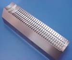
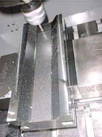
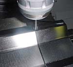
High speed machining was used to produce this die segment in just under 12 hours—an improvement over the previous method for producing it, which relied on EDM. The HSM process uses tools ranging from 10 mm down to 1 mm in diameter.
So much has been said and written about high speed machining in the past few years, you'd think everybody would know about it by now. I didn't write those words this year, I wrote them in 1996. Since the appearance of my first article on high speed machining for this magazine, a lot about HSM has changed. A lot more has remained the same. One thing that hasn't changed is the amount of confusing and contradictory information.
It's been exciting for me to watch so many shops succeed with high speed machining over the past 6 years. I have seen shops increase productivity by many multiples simply by changing their processes and strategies. One shop I worked with used to take 20 labor hours to make a 12 by 24 inch forging die. The process included electrode machining, EDM and hours of polishing time. By changing the process, the shop was able to machine the entire die on the same machine formerly used to make the electrode. EDM was completely eliminated. Also eliminated was the recast layer that had to be removed after EDM. When the die was produced on the machining center, the finish directly from the machine was 30 RMS, which is better than what the shop needed. And total processing time was reduced to just 1 hour.


High speed machining is a topic worth revisiting not because of what has changed, but because there are still many shops that can benefit from it. A large number of shops are still trying to decide if they should invest in high speed machining. Others believe it's a myth. Still others have bought high speed machines, but they're trying to get them to live up to their billing.
Following an outline similar to that of the article from 6 years ago, here is an up-to-date introduction to high speed machining as it relates to the die/mold industry.
What's So Different About HSM?
Answer: not much. We replace a process consisting of a few slow and heavy cuts with a process consisting of more numerous, faster, lighter cuts. The chips produced are much smaller, but they come off a whole lot faster. The main reason high speed machining works is the smaller depth of cut. The smaller depth means less heat is generated in the cut. With less heat in the cut, the rpm can be dramatically increased. And since the chip load per tooth stays the same or is even increased, a much higher feed rate can be achieved to correspond with the increased rpm.
Example:
Conventional rough machining with 2 flute 1/2 inch ball nose end mill
Speed: 900 rpm
Feed: 14 ipm
Chip load: 0.008 ipt
Depth of cut: 0.25 inch
Step-over: 0.5 inch
MRR: 1.75 cubic inches per minute
High speed machining with the same diameter tool
Speed: 9,200 rpm
Feed: 147 ipm
Chip load: 0.008 ipt
Depth of cut: 0.05 inch
Step-over: 0.25 inch
MRR: 1.83 cubic inches per minute
From this example you can see that the metal removal rate improves. One other benefit that isn't apparent from the data is that the net shape after machining is much closer to the actual shape of the part, so that in some cases the semi-finish passes can be eliminated. This saves time, as well as the cost of the tooling that would have been needed.
HSM's heat management also explains why the techniques can be used to machine much harder materials. In the past, machining hardened materials required the rpm to be reduced, because cutting the harder material created more heat. With rpm reduced below 900, cycle time would have been longer than that of EDM—which is why EDM was chosen for machining after heat treatment. But with HSM, reducing the rpm to make up for the heat generated is not that big of a deal. We reduce the rpm from 9,200 to 6,000 in the example above to maintain the heat at acceptable levels. This will increase the cycle time compared to machining in the soft state, but the cycle time will surely beat that of EDM. In many cases the actual die can be machined in the same cycle time required to make the electrode.
How Fast?
When is machining considered to be high speed machining? My answer has changed over the years. I used to say that HSM starts at 1,200 surface feet per minute (sfm), but what I found was that many customers that only have 4,000 rpm spindles thought they could not perform HSM. I now think of HSM as a process instead of a given number for sfm, rpm or feed rate. Many variables affect what rpm or feed rate would qualify as "high speed." Some of the important factors are machine type, spindle, control speed, toolholder, cutting tool and the biggie—tool extension (how far the tool sticks out from the holder).
None of these factors can be overlooked, but some are more important than others. Tool extension is the most important because longer extension translates to less rigidity in the process. Less rigidity makes it likely that more heat will be generated from the vibration. With more heat, the rpm will have to be reduced. Similarly, the toolholder is important because run-out will create vibration and generate heat.
New tool coatings being developed today will withstand more heat, but there is a maximum amount of heat a particular coating can handle.
The machine type, spindle rpm and control speed are only important in that they may limit top speed. But as I mentioned, I have seen success on older, 4,000 rpm machines.
Tool Selection
The cutting tool is an important factor in HSM. The substrate, grind and coating will determine how much heat the tool can handle. These characteristics have all seen changes in the past 6 years.
The substrate will determine rigidity. Most cutting tools that are designed for HSM are now made of sub-micrograin carbide. In simplest terms, this means the carbide particles are smaller than 1 micron. The smaller grain sizes make for a tool with more density, which relates directly to rigidity.
The grind of a cutting tool can control heat and also increase rigidity. The tools being manufactured today that seem to work best have large core diameters for rigidity and an edge preparation that is designed with heat and strength in mind. The core diameter is the thickness of the part of the tool that doesn't include flutes. The chips generated in HSM are smaller, so they do not need as much area for evacuation. This allows the cutting tool manufacturer to maintain a larger core diameter for rigidity. The edge preparation (hone and/or land) must be designed to allow most of the heat generated in the cut to be dispersed into the chip instead of into the body of the tool. The edge prep should also create a minimal amount of deflection, since deflection creates vibration, which, again, creates heat.
The coatings available for HSM have probably made the largest leap forward. The coating most used in HSM, TiAlN, has many different variations. The variation I have seen the best results with is actually an AlTiN coating. This means there is more aluminum than titanium in the coating. The aluminum in the coating creates aluminum oxide during the cut. The aluminum oxide helps to plasticize the metal at the cutting zone, which assists in putting the heat into the chip at the same time that it protects the cutting edge itself. This coating can be used in slower applications as well, which makes it very versatile.
Programming
I don't think programming is more difficult for HSM, just more time consuming. The programmer needs to do more thinking up front to develop the proper strategy. Once the strategy has been determined, the features of today's CAD/CAM software make it relatively easy to generate the appropriate tool paths. Techniques typically used in HSM have long been possible with many programming systems, but now those technologies are easier to use. The technique that should be used the most, particularly on three-axis machines, is "Z-level" machining. This approach slices the part into incremental levels and machines each level in turn. Most milling CAD/CAM systems do this very well. For steels, the drop between Z levels should not be more than 10 percent of the diameter of the cutter. (Your cutting tool supplier should have charts for the different materials and hardness ranges that are recommended for HSM with their tools.) The most difficult part of each level is the initial engagement into the material. The two best engagement methods are "ramping" and "helical." Both methods are used to minimize shock to the cutter as it enters the material. During roughing, the angle of engagement for either the ramping or helical method should range from 1 to 3 degrees for a smooth entry into the material.
Fast In The Curves
While an older machine can be used to begin performing HSM, particular aspects of the machine's design become more important as speed and feed rate increase.
Machine tool manufacturers are offering more powerful controls, but the control is not the only aspect of the machine that determines accuracy at high feed rates. The machine's ways, its ball screws (unless it has linear motors) and even the machine foundations need to be designed for high feed rates. Just because the control has the power to read and process the program quickly does not mean that the machine itself will be able to follow the moves accurately. Wear is also a potential problem. The acceleration and deceleration needed to change directions quickly can take a toll on a machine not designed to handle it. Also, the machine ways and ball screws need to be able to manage or stand up to the heat generated by high feed rates. The heat created in the spindle by high rpm must be dealt with as well. If the heat is not controlled, the machine will absorb it, and thermal expansion will compromise accuracy.
The Big Picture (6 Years Later)
If you think of HSM as a process instead of a technology, it's easier to see that even an older machine can perform it. A newer machine may be capable of more impressive results, but even on an older machine, a change in the process can decrease cycle time and cost while increasing accuracy. Just by starting with a little understanding alone, some of the benefits of HSM can be yours.
About the author: Ron Field is a vice president for cutting tool maker Millstar of Bloomfield, Connecticut.


Related Content

10 Tips for Titanium
Simple process considerations can increase your productivity in milling titanium alloys.
Read More
New Machining Technology Works With Old to Restore WWII Submarine
A set of donated boring bars that can be used in a 1954 boring head will enable volunteer machinists to recreate a pair of binoculars for the USS Pampanito.
Read More
How to Mitigate Chatter to Boost Machining Rates
There are usually better solutions to chatter than just reducing the feed rate. Through vibration analysis, the chatter problem can be solved, enabling much higher metal removal rates, better quality and longer tool life.
Read More
Choosing Your Carbide Grade: A Guide
Without an international standard for designating carbide grades or application ranges, users must rely on relative judgments and background knowledge for success.
Read MoreRead Next

The Cut Scene: The Finer Details of Large-Format Machining
Small details and features can have an outsized impact on large parts, such as Barbco’s collapsible utility drill head.
Read More

3 Mistakes That Cause CNC Programs to Fail
Despite enhancements to manufacturing technology, there are still issues today that can cause programs to fail. These failures can cause lost time, scrapped parts, damaged machines and even injured operators.
Read More