What Should You Consider When Turning Micro Parts on a Lathe?
Various factors, including the machine, cutting tools and operator, must be taken into consideration to turn very small parts.

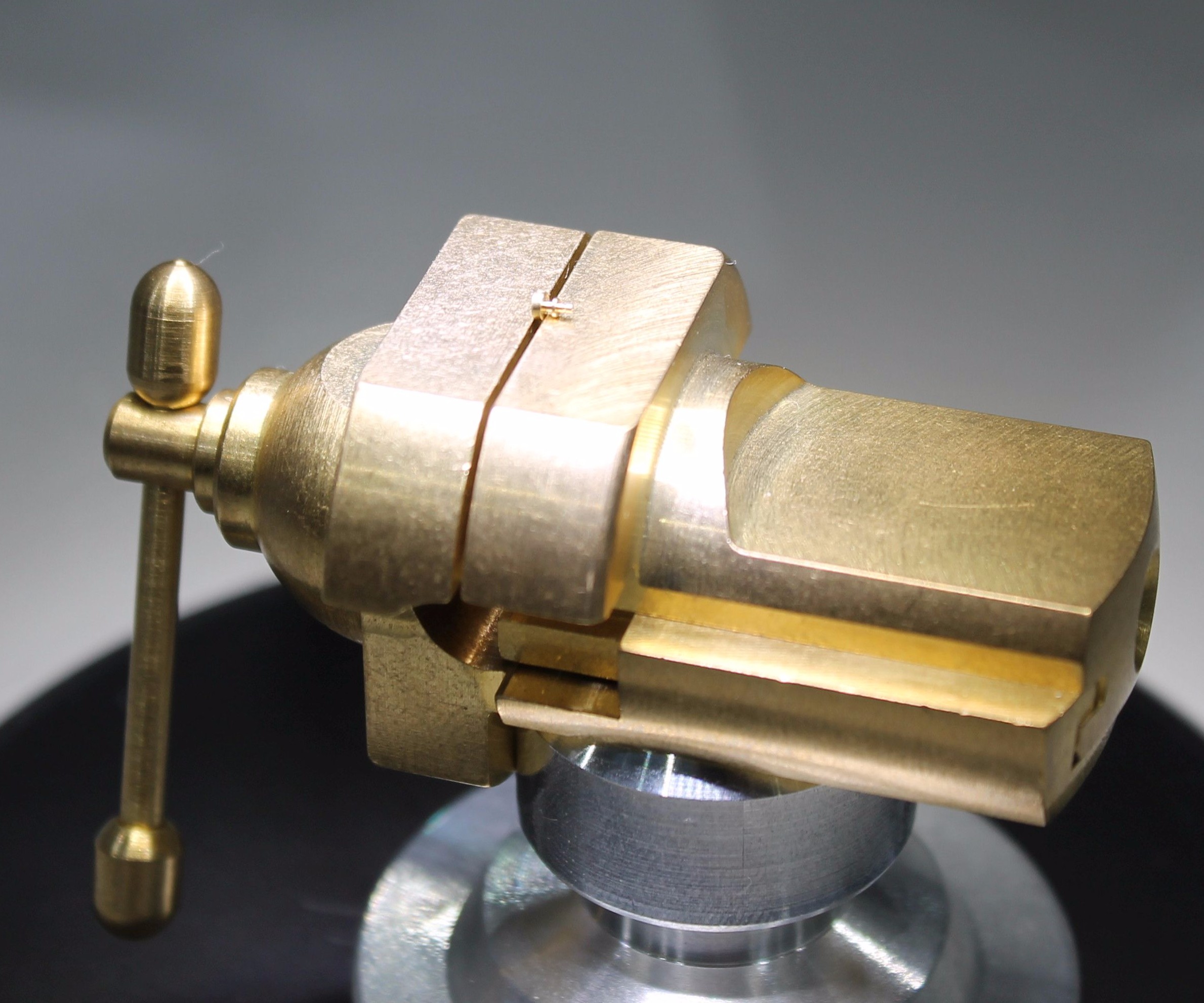
The length of this part is 0.08 inch. Effective turning of this part requires one to look at the entire machining process, which includes machine, cutters and operator.
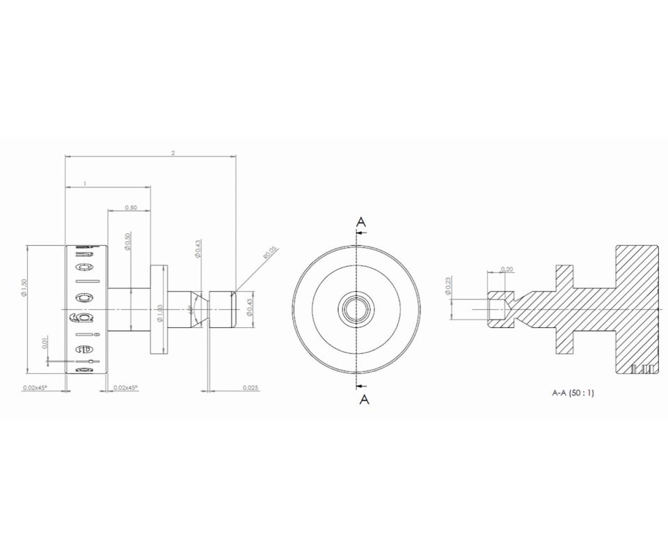
Horn’s S274 µ-Finish system, as well as its Supermini and DS micro end-mill system, was used to machine this tiny component (numerical values are in millimeters).


The manufacture of miniature parts is not new, but over the past several years, there has been a trend toward continued miniaturization in a range of industries, including aerospace, automotive, medical and electronics. Mike Smoody, application engineer at HORN USA, says to machine a part with outer diameters (ODs) as small as 0.0039 inch, one must look at the whole process, because there are quite a few challenges. The slightest variation in the process caused by material or cutting tool characteristics, thermal variations in the machine, or vibrations will have a direct impact on the ability to produce features of this type.
There are many different definitions for micromachining. For Horn, micromachining on lathes means ODs as small as 0.0039 inch, inner diameters (IDs) as small as 0.0078 inch and plunge cuts from 0.0197 inch. In addition, these operations require extremely low depths of cut (less than 0.0039 inch), extremely low feed rates (0.00019 ipm), low cutting forces and a demand for high surface qualities.


Several factors must be considered to develop a process to successfully machine parts this small. As Mr. Smoody explains here, three of these are the operator, the machine and the cutting tools:
Operator
Not every operator is made for this type of work. Besides being able to machine micro features and parts, simply handling micro parts and tools can pose unique challenges. Accuracy takes on a completely new meaning. For a process with a tolerance of less than 1 micron, repeatability is not easily achieved. The operator must be calm and patient.
Machine
To achieve the precision required for effective micromachining, the machine’s spindle design is critical. The high-speed spindles on most new machines are oil-cooled, and should offer great rates of acceleration and deceleration, while minimizing the onset of vibration.
To collect the small workpieces, some machine tool manufacturers offer a non-contact, air-blown collection chute, which also separates chips from the machined components. Moreover, high-pressure coolant systems clear chips off the workpiece and stabilize the temperature of both the cutting tool and part being machined during the operation. Mist collectors should filter the cutting fluid mist from the work area, too.
Cutting Tools
In general, tools for micro-turning operations require extreme sharpness, good gliding properties, extremely high surface quality, high change-over precision, high tip-height accuracy and a stable interface. Tool breakage is more of a concern in micromachining, because any minor offset can cause a tool to snap.
Influencing factors on the process are the insert clamping, substrate, micro geometry (chamfer size or edge radius) and coating. Due to the extremely low feed rates, the insert’s sharp cutting edges with a radius of 1.44 microns and an angle of 80 degrees, for instance, ensure low cutting forces, good surface finish and high dimensional accuracy. Conversely, a cutting edge with a radius of 50 microns is recommended for rough machining or interrupted cutting.
The result also depends on the stability of the system as a whole. When an insert is clamped, care must be taken to ensure this is done with the highest levels of stability and precision. In addition, when dealing with very small part diameters, tool-center-height accuracy is extremely important. Ideally, the setup should be such that the operator does not have to adjust the center height when indexing the insert. To that end, Horn µ-Finish inserts are manufactured with a center height tolerance of ±0.0001 inch to ensure this accuracy while indexing.
A sharp cutting edge improves machining quality by minimizing vibration tendencies. To maintain a sharp cutting edge, an uncoated insert would be ideal, but many workpiece materials to be machined require insert coatings. (In addition, uncoated inserts typically produce lower cutting forces compared to coated ones.) In a case of coated cutting tools, surface pre-treatment and coatings significantly influence the cutting-edge micro geometry, especially in machining with small-diameter tools.
As a result, Horn has developed the S274 tooling system with the µ-Finish inserts. Each cutting edge is inspected under 200x magnification as an additional quality control measure. This attention to detail ensures that once the tool has been set up, no further height adjustments are required when replacing a worn insert.
The micro-grain carbide structure and specially designed geometries are well suited for machining steels, stainless steel and brass. A new coating type AC25 (developed for micro-turning, grooving and parting-off applications) resists wear and build-up of material on cutting edges.
Horn’s S274 µ-Finish system, as well as its Supermini and DS micro end-mill system, was used to machine the tiny shaft component shown above, which has a length of 0.08 inch. The first facing operation with the S274 system was performed with a cutting speed of 80 meters per minute and a feed rate of 0.003 millimeters per revolution. The same tool system was used for longitudinal turning, grooving and parting-off operations.
For internal-profiling operations (for a diameter of 0.009 inch), the Supermini system was used at a cutting speed of 12 meters per minute and a feed rate of 0.003 millimeters per revolution. Mr. Smoody says the Supermini cutting tool’s new substrate, coating and edge preparation increase tool life. For example, he says the EG35 grade has demonstrated as much as 60 percent longer tool life when turning cobalt chrome at 1,000 N/mm2. This grade enables the tool to machine diameters ranging from 0.008 inch to 0.268 inch in tough materials while increasing return on investment. In addition to sharp, clean, chip-free edges, maintaining the proper feed rate will help keep chip removal problems at bay, he adds.


Related Content

Choosing Your Carbide Grade: A Guide
Without an international standard for designating carbide grades or application ranges, users must rely on relative judgments and background knowledge for success.
Read More
Toolpath Improves Chip Management for Swiss-Type Lathes
This simple change to a Swiss-type turning machine’s toolpath can dramatically improve its ability to manage chips.
Read More
New Machining Technology Works With Old to Restore WWII Submarine
A set of donated boring bars that can be used in a 1954 boring head will enable volunteer machinists to recreate a pair of binoculars for the USS Pampanito.
Read More
Threading On A Lathe
The right choices in tooling and technique can optimize the thread turning process.
Read MoreRead Next

3 Mistakes That Cause CNC Programs to Fail
Despite enhancements to manufacturing technology, there are still issues today that can cause programs to fail. These failures can cause lost time, scrapped parts, damaged machines and even injured operators.
Read More

The Cut Scene: The Finer Details of Large-Format Machining
Small details and features can have an outsized impact on large parts, such as Barbco’s collapsible utility drill head.
Read More