
Hydraulic Workholding Devices Allow Total-Perimeter Machining
Having access to the entire perimeter of a part minimizes set ups because shops can machine five sides of the part in one fixturing. This enables shops to reduce the total number of manufacturing operations, the number of times parts must be handled, the potential for part damage due to excessive handling and the o
.jpg;width=70;height=70;mode=crop;format=webp)
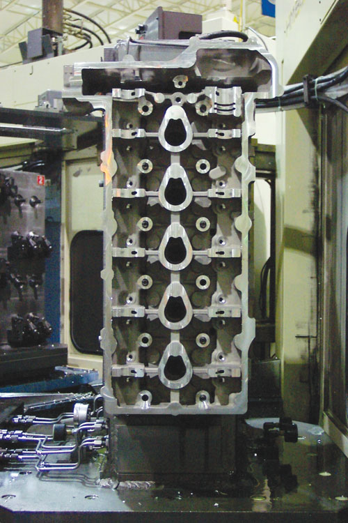

Large cylinder heads are good candidates for this through-hole workholding method. There are seven clamps on each side of this dual-sided fixture that hold the cylinder heads for machining operations.
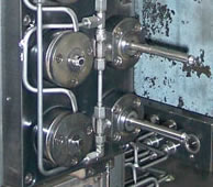
The through-hole clamps shown above expand their arbors and then pull cylinder heads against the fixture.


Having access to the entire perimeter of a part minimizes set ups because shops can machine five sides of the part in one fixturing. This enables shops to reduce the total number of manufacturing operations, the number of times parts must be handled, the potential for part damage due to excessive handling and the overall manufacturing cost. However, five-sided machining is often difficult to accomplish using conventional swing clamps, edge clamps and slide clamps that can prevent access to various part features that require milling, drilling, turning or other operations.
Innovative Technologies Unlimited (Clarkston, Michigan) has developed two devices that it says allow total-perimeter machining. Its Diametric Wall Clamp (DWC) and Edge Gripping Clamp (EGC) use an expanding arbor inserted in a part’s machined or as-cast blind or through hole to secure the part tightly against a fixture for machining. Not only does this clamping method allow access to five sides of a part, it also directs clamping forces directly on a part’s locating surface. This reduces the chance that critical features might distort, which can be an issue when using conventional clamping methods.
In most applications, multiple DWC or EGC clamps are installed on fixtures to hold large castings, forgings or blanks on machining centers or vertical lathes. The DWC version is designed for holding parts that have blind holes. Once a part is loaded onto the fixture, the DWC arbors inside the part’s holes expand via hydraulics or pneumatics, forcing grippers to contact hole walls. The clamps then retract their arbors, pulling the part tightly against the fixture and precisely positioning it for machining.
The EGC version functions in much the same way as the DWC except that the clamp’s arbor extends past the end of a through-hole. When a part is loaded on a fixture, the clamp arbors expand and pull against the back side of the part to secure the part against the fixture. The EGC version is shown on this page clamping a cylinder head to a dual-sided fixture. (A link to an online animation demonstrating both clamp versions is found in the Learn More box to the left.)
The clamps are made from 8620 hot-rolled steel that is case-hardened to prevent external wear during normal manufacturing operations. The clamps are powered by double-acting hydraulic or pneumatic cylinders that use neither springs nor other mechanical returns that could freeze or break during operation. They have a protective top cover and O-ring assembly that keeps chips out of the unit.
The clamps can be used in either a horizontal or vertical part orientation. Pull tests performed at an independent laboratory determined that clamping force varied depending on workpiece material. For example, the maximum measured pull forces for cast iron, steel and aluminum were 501, 574 and 634 pounds, respectively. The number of clamps used on a fixture is determined by the total amount of pull force that is specified for the machining application.
Related Content
-
Medical Shop Performs Lights-Out Production in Five-Axes
Moving to five-axis machining enabled this shop to dramatically reduce setup time and increase lights-out capacity, but success relied on the right combination of workholding and automation.
-
Simple Workholding for Robotic Automation
Robotic automation relies on reliable workholding, and these modular pneumatic jaws make it simple.
-
When To Use A Collet Chuck
Don't assume the standard chuck is the right workholding for every lathe application.


