
Insert Grade Reduces Tool Wear In Demanding Cut
When shops experience insert wear, they often turn to their trusted cutting tool suppliers for a solution. In this case, however, Seco Tools not only supplied one customer with a new grade, but also conducted an extensive investigation into the shop’s processes to help it use that grade as effectively as possible.
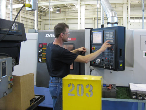
The flanges are machined on this Doosan 240 CNC lathe at 300 sfpm and 0.01 ipr.
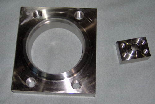
Due to the rectangular shape of the flanges shown here, the shop had to take severely interrupted cuts during turning operations. Seco’s Duratomic TM4000 grade has helped the manufacturer resist the resulting wear and edge breakdown.
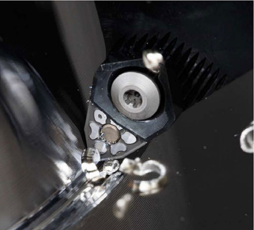
Seco supplied Main Manufacturing with its TM4000-grade inserts equipped with the MF4 chipbreaker, which is designed to provide consistent chip formation and breakage.


Providing the best possible product is important to stay ahead in today’s competitive marketplace, but many suppliers also view the ability to enhance clients’ profitability through value-added customer service as an essential component for success. While Seco Tools is no exception to his philosophy, the cutting tool manufacturer says it recently went above and beyond the norm to address insert failure experienced by one customer on a troublesome stainless steel application. In the end, the supplier’s detective work enabled that customer to reduce costs and machining time on the application by 85 percent and 52 percent, respectively.
The customer, Main Manufacturing, is a family-owned business that started in 1959 as a manufacturer of hydraulic presses. During the 1970s, the company began to transition away from building presses, choosing instead to focus on hydraulic flanges and associated components. In 1999, the company moved to a new, 48,000-square-foot facility in Grand Blanc, Michigan, where it currently houses 200 machines. It produces more than 15,000 parts, half of which are specials or non-cataloged requests. Typical part runs range from 5 to 500 pieces.


Flanges are a critical part of any hydraulic system. The company’s flanges are used for a variety of equipment built to withstand pressures ranging from 3,000 to 8,000 psi, including oil rigs, stamping presses, wave pools, lubricating systems and theme park effects. One primary goal is to turn around flange orders within 3 days (including 1 day for processing). To achieve this, operators set up machines in less than 15 minutes and run eight to 10 production jobs per day.
Main has been using Seco cutting tools for more than 10 years, mostly for drilling and turning applications. This particular job involves a high-pressure flange machined from 304 stainless steel on a Doosan 240 CNC lathe. The flange begins as a 2.25-inch by 1.5-inch rectangular plate, which is rough-faced down to a hub in the center of the part at 300 sfpm and 0.01 ipr. The company originally machined the flanges with three 0.1-inch passes and a final pass at a 0.05-inch cutting depth. The interrupted cut caused significant wear and edge chipping on the cutter, limiting tool life to approximately 1.5 parts per insert.
Seco was originally called in to supply tools and expertise for milling a ring groove into the flange. However, the cutting tool manufacturer was in search of a demanding interrupted cut application to test out its new Duratomic turning grades for stainless steel, particularly the TM4000 grade. Seco sales and application specialists Joel Henige and Todd Miller asked Main if they could give the new grade a try.
"Cutting a square in a turning application is a real challenge for inserts," Mr. Henige says. "An interrupted cut can cause failure in even the toughest multi-layer coating, but we felt confident that the Duratomic coating could improve Main’s performance."
Duratomic coatings improve toughness and wear resistance by altering the crystal structure at the atomic level, the company says. Through a combination of the coating and a graded substrate, the TM4000 grade is designed to maximize toughness in the cutting zone without compromising the strength of the base material. According to the manufacturer, lab tests demonstrate that this construction substantially improves resistance to cratering and edge breakdown.
The initial decision was to run the TM4000 at the same parameters as the tool previously used for the flange application. To everyone’s surprise, however, it performed no better than the other insert. Believing that the grade was capable of higher machining parameters, the applications specialists increased the cutting speed to 650 sfpm and incorporated the MF4 chipbreaker.
The MF4 is designed to provide consistent chip formation and breakage in stainless steel turning and other ISO materials. According to Seco, its main advantage is a positive cutting angle that significantly reduces cutting forces to allow higher speeds and increased productivity. With the MF4 and new cutting parameters, the team tripled tool life.
However, this was far from the results the team had anticipated. Mr. Miller and Mr. Henige examined the inserts under a magnifying loop, but couldn’t find any problems. At this point, the two decided to take a hard look at the tool under a microscope that provides 60 times the optical power of the loop. "I have to say that we seldom see this kind of investigative service from our suppliers," says Terry Bettinger, Main Manufacturing’s plant supervisor.
The microscope revealed edge chipping that had eluded Mr. Miller and Mr. Henige with the magnifying loop. They discovered that the chip flow was eroding the back of the land on the MF4. By examining the wear pattern, the two also noted that a larger nose radius would help increase edge strength. They recommended increasing the feed rate to 0.016 ipr using a 0.0468-inch radius. Cutting speed remained at 650 sfpm, as the team hadn’t discovered any other heat-related problems.
"We were pleased," says Main Manufacturing machinist Craig Bendle. "Productivity doubled relative to our original setup, and tool life jumped to seven parts per corner—seven times better than we were getting before."
But Mr. Henige and Mr. Miller weren’t yet done with their analysis. Another pass under the microscope revealed that insert failure was now being caused by thermal cracking. Large differences in temperature between the cutting edge and the insert can cause cracks that run perpendicular to the cutting edge, Mr. Henige explains. These temperature fluctuations are common in interrupted cutting applications, which tend to generate high heat during the cut.
To further improve the process, the team decided to run the application dry because coolant, which was water in this case, can exacerbate thermal cracking. As a result, tool life doubled again to 15 points per corner, and any worn edges were caused only by normal abrasive flank wear. With the Seco teams’ recommendations, Main went from removing 3.6 cubic inches per minute to 12.483. With in-cut time reduced by half, part output increased from 17 pieces per hour to 54 pieces per hour.
"We run this job quite frequently and total about 3,000 flanges per year," says Bob Mackey, general manager at Main Manufacturing. "But what we truly find exciting is that we can take what we’ve learned from this experience and apply TM4000 to hundreds and maybe even thousands of similar jobs that we run."


Related Content

Choosing Your Carbide Grade: A Guide
Without an international standard for designating carbide grades or application ranges, users must rely on relative judgments and background knowledge for success.
Read More
How to Tackle Tough Angled Pocket Milling With Two Tools
Milling a deep pocket with a tight corner radius comes with unique challenges, but using both a flat bottom drill and a necked-down finishing tool can help.
Read More
A New Milling 101: Milling Forces and Formulas
The forces involved in the milling process can be quantified, thus allowing mathematical tools to predict and control these forces. Formulas for calculating these forces accurately make it possible to optimize the quality of milling operations.
Read More
Best Practices: Machining Difficult Materials
Cutting hardened steel, titanium and other difficult materials requires picking the right tools, eliminating spindle runout and relying on best practices to achieve tight part tolerances.
Read MoreRead Next

The Cut Scene: The Finer Details of Large-Format Machining
Small details and features can have an outsized impact on large parts, such as Barbco’s collapsible utility drill head.
Read More
3 Mistakes That Cause CNC Programs to Fail
Despite enhancements to manufacturing technology, there are still issues today that can cause programs to fail. These failures can cause lost time, scrapped parts, damaged machines and even injured operators.
Read More
