
Keeping Accuracy Within Reach
Part quality is at risk if a machining center cannot hold tolerances at the farthest reaches of its work envelope. This makes volumetric accuracy a key indicator of a machine's performance. One machine tool builder discusses the implications.


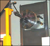
Although calibrating a machine's volumetric accuracy is not easy, the use of ballbars and other metrology techniques has made it less disruptive.
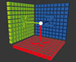
The work envelope of a horizontal machining center can be imagined as a box- or cube-shaped region in space. This region defines the reach of the machine tool for effective cutting, but accuracy may not be uniform at every point within this envelope because of imperfections in the machine's construction.
For a machine tool to achieve a high level of volumetric accuracy, the way system must be constructed for straight axis movement with minimum pitch, yaw and roll. These errors must be detected and corrected during the assembly of the machine at the factory.
Machine shop owners and managers face many challenges. But one that can be the most troublesome is a machining center that fails to produce accurate parts.
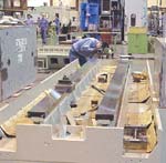
One cause of bad parts could be problems with the machine's volumetric accuracy. One example is when a shop gets in a large part that occupies the maximum of the machine's work envelope. The machine is able to hold tolerances within a specific area of the work envelope, but when the machine is cutting at the outer reaches of this area, features in this vicinity on the large part are not produced to tolerance. The same thing happens when small parts are located on corresponding portions of a tombstone fixture that takes up most or all of the work envelope. These parts are machined less accurately than those clamped elsewhere on the tombstone. What is going on here?


The culprit could be deficiencies within the machine tool's volumetric accuracy that go unnoticed until a part or parts are placed in the farthest reaches of the machine's work envelope. Each machine tool has a work envelope where a part can be placed and effectively cut. In a three-axis machine, the work envelope is made up of the total area that the cutting tool can reach with movement of the three axes.
Another way to understand volumetric accuracy is to picture two points of space within a cube. In theory, these two points have a perfect position in relationship to each other. They could be exactly 1,000 mm apart in the X axis, 500 mm apart in the Y axis and 300 mm apart in the Z axis. The first position is 0, 0, 0 in X, Y and Z, and the second position is defined by the values given above. If the machine can move to the second point with absolutely no deviation in relationship to the first point, its volumetric positioning would be perfect, and theoretically, any point the machine can reach should have a true position in the work envelope.
“However, the reality is that if you start at the X, Y, Z zero position, and a tool is driven to a point at this defined position, it doesn't exactly go there, because of positional error in ballscrews or linear motors or whatever device is driving it there,” says Scott Walker, president of Mitsui Seiki (USA) Inc. (Franklin Lakes, New Jersey). This happens, he explains, because there are geometrical inaccuracies inherent in any assembly that prevent it from getting there. Machine geometry is a function of moving a certain amount of mass along the machine's way system. This mass needs to move in a straight direction without pitch, yaw and roll, because any variation is amplified as the mass moves further and further along the machine's way system.
Mr. Walker adds, “You want to make sure that the machine's dynamic volumetric capability is at least 50 to 80 percent tighter than the part tolerance. In high-precision machining, most people use an 80 percent capability. For instance, if I have to produce a part to thousandths of an inch, such as an aircraft gearbox, the machine tool must be capable of true positioning to 0.0002 inch. That way I have 0.0008 [inch] to play with for all the other things, such as heat distortion, that are affecting the quality of the part.”
Built-In Precision
Mr. Walker says that volumetric accuracy has to be built into a machine before it's purchased. In fact, volumetric accuracy is dependent on the part application and must be tailored accordingly, as in the case of exceptionally heavy workpieces (see box on page 76).
To reduce pitch, yaw and roll that affect the machine's volumetric accuracy, Mr. Walker believes that the machine has to be hand-scraped along its ways. To check hand scraping for accuracy, an optical device called an autocollimator is used to analyze the pitch and yaw. By looking through this telescope-like device, one can detect misalignment by the position of the cross hairs in the autocollimator's sight. Movement of the cross hairs up and down indicates pitch error, whereas movement left or right indicates yaw error in the way surface. Roll error is measured with a precise spirit level. Typically, the autocollimeter is moved 100 mm along the way surface to measure pitch and yaw error at each interval. Then the spirit level will be moved along the way system to measure roll error at the same interval. This surface must be hand-scraped to reduce those values to acceptable tolerances.
Also, when heavily massed machine tool components are placed together during assembly—for example, when a four-ton column is placed on the machine's bed—the column compresses and bends the bed. For the column to track straight, a slight bow is produced in the way system to compensate for this distortion. Then, when the column is added to the machine tool, the column's weight compresses and allows the axis to run flat or straight.
If the X, Y, and Z axes can have reduced pitch, yaw and roll; their weight and their influence on each other can be compensated for; and the axes now track straight, then the straightness can be measured in arcseconds. A very high-accuracy machine would have straightness arcsecond tracking of less than 2 arcseconds, which would be considered excellent.
Once the three axes on a typical three-axis machine track straight, then the last adjustment necessary is to get good perpendicularity of those axes. If the machine has precise perpendicularity and straightness, then when the cutting tool is tracking through space, it will have excellent true positioning in a defined area. In short, the machine tool's volumetric accuracy will be high.
Positioning repeatability and volumetric accuracy are related, says Mr. Walker. Repeatability, however, describes a machine's ability to return to a single point in space along one of the machine's axes, whereas machining accuracy involves many points tied together. “Repeatability was a big issue in the early days of building machine tools, when ballscrews were not preloaded as they commonly are today,” notes Mr. Walker. Thus, he concludes, repeatability no longer holds the relevance it once did for machine tool buyers.
Precision Performance Standards
In addition to applying standards set by national institutions to help end users define what a specific machine tool characteristic or capability should be, Mr. Walker says that builders also apply their own standards for measuring a machine tool's accuracy. For example, certain builders have a perpendicularity standard that uses a cylindrical square to measure the machine's perpendicularity. Likewise, they use a ceramic square placed on the table to check for the flatness of a pallet as it rotates in relationship to the spindle.
Builders will measure a group of tolerances that they specify in their production plan, allowing them to give the machine's true positioning in some number. For example, they may state that the machine is capable of positioning 20 microns or better in a meter cube, or that the machine is capable of positioning 75 microns or better in a 1,000-mm cube. “True position is very difficult to measure, because it states that anywhere I position a point off the spindle, such as the tip of a drill, this position will not deviate in relation to a X, Y, Z location specified somewhere in space by any more than 20 microns,” explains Mr. Walker.
According to Mr. Walker, machine tools are often designed and manufactured to have a “sweet spot” in their work envelope where they have the greatest accuracy. “You can't have perfect perpendicularity and precise roundness capabilities because of the way the machine is designed for one or many applications,” he says. If critical tolerances are confined to certain portions of the machine's work envelope, special attention must be devoted to the machine's precision in that portion of its work envelope.
The situation becomes more complex when discussing a five-axis machine, Mr. Walker says. For example, a number of five-axis trunnion-type machines are on the market. However, some of these machines have five-axis capability to within 10 arcseconds, whereas others are within 0.5-arcsecond accuracy. “The problem with five-axis machines is that you have issues of axis orbit, which is the axis rotation orbiting between two rotating axes,” he explains. “Hysteresis is also a concern in motor reversal, because you have to put a lot of energy into the motor to drive it, and then when the motor has to slow down and reverse direction, you have to take all that energy out, which takes time. This creates servo lag and will affect the true dynamic positioning capability in the machine's work envelope.”
To solve these problems, Mr. Walker contends that machine tools need to be hand-scraped with fitted components, and hysteresis must also be controlled by tuning servos and manipulating the velocity and positional data for smooth motion and good control of the machine masses that are being moved around in space.
Although software is used by machine tool builders to offset machine inaccuracies resulting from spindle growth from heat, this software can't be used to offset inaccuracies of axis movement in the work envelope, because these inaccuracies can change depending on the part or parts being machined.
Measuring The Machine And The Part
Although measuring a machine tool's volumetric accuracy is very difficult, Mr. Walker describes two approaches to accomplishing this task.
Dr. Charles Wang, president of Optodyne, Inc. (Compton, California), has developed one method for measuring machine tool volumetric accuracy. According to Dr. Wang, procedures for volumetric calibration have been set forth in ASME B5.54 and ISO230-6 volumetric machine tool performance measurement standards. However, machine tool users have been reluctant to adopt volumetric calibration because following these procedures necessitated taking the machine out of production for 2 or 3 days. Optodyne's Laser Vector Technique for volumetric calibration and compensation reduces the time factor to 2 or 3 hours, making it an attractive option for measuring this aspect of a machine tool's performance.
Renishaw Inc. (Hoffman Estates, Illinois) also has equipment to measure the volumetric accuracy of a machine tool. Clive Warren, business manager of the calibration products division, lists three devices that will give a user an accurate measurement of a machine tool. One is the ML10 Gold Standard laser measurement system used for comprehensive accuracy assessment of machine tools, CMMs and other position-critical systems. Another is the QC10 Ballbar System used for quickly checking CNC machine tool performance on a regular basis. The last is the machine checking gage. Mr. Warren says that all of these systems are portable, and the ballbar and machine checking gage are affordable, automated and readily used by small shops as well as large ones.
The Full Range
To machine parts accurately throughout a machining center's full range, it must exhibit the adequate volumetric accuracy. The easiest way that a buyer can make sure that a machine tool's volumetric accuracy is adequate is to cut sample parts where they are located in the work envelope and to check them to verify that tolerances are met. As Mr. Walker summarizes it, only machine tools designed and built with the precision to achieve high volumetric accuracy can hold tight tolerances regardless of where the cutting tool goes within the envelope.


Related Content

Horizontal Turning Center Ready for High Production
Romi Machine Tools’ new GL300 S features high-power torque and feed force and is built with a robust monoblock base for ultimate rigidity and precision.
Read More
Shop Replaces Two Verticals With One Horizontal
By trading two VMCs in to help finance the purchase of a new HMC, this shop was able to significantly increase production and move to lights-out machining.
Read More
Translating a Prototyping Mindset to Production
The experimental mindset that benefited BDE Manufacturing Technologies as a prototype job shop has given it an adaptable edge as a production facility.
Read More
The Debut of an HMC Series
The FH5000 Series from JTEKT Toyoda is compromised of three high-speed horizontal machining centers.
Read MoreRead Next

The Cut Scene: The Finer Details of Large-Format Machining
Small details and features can have an outsized impact on large parts, such as Barbco’s collapsible utility drill head.
Read More

3 Mistakes That Cause CNC Programs to Fail
Despite enhancements to manufacturing technology, there are still issues today that can cause programs to fail. These failures can cause lost time, scrapped parts, damaged machines and even injured operators.
Read More