.jpg;width=70;height=70;mode=crop;format=webp)
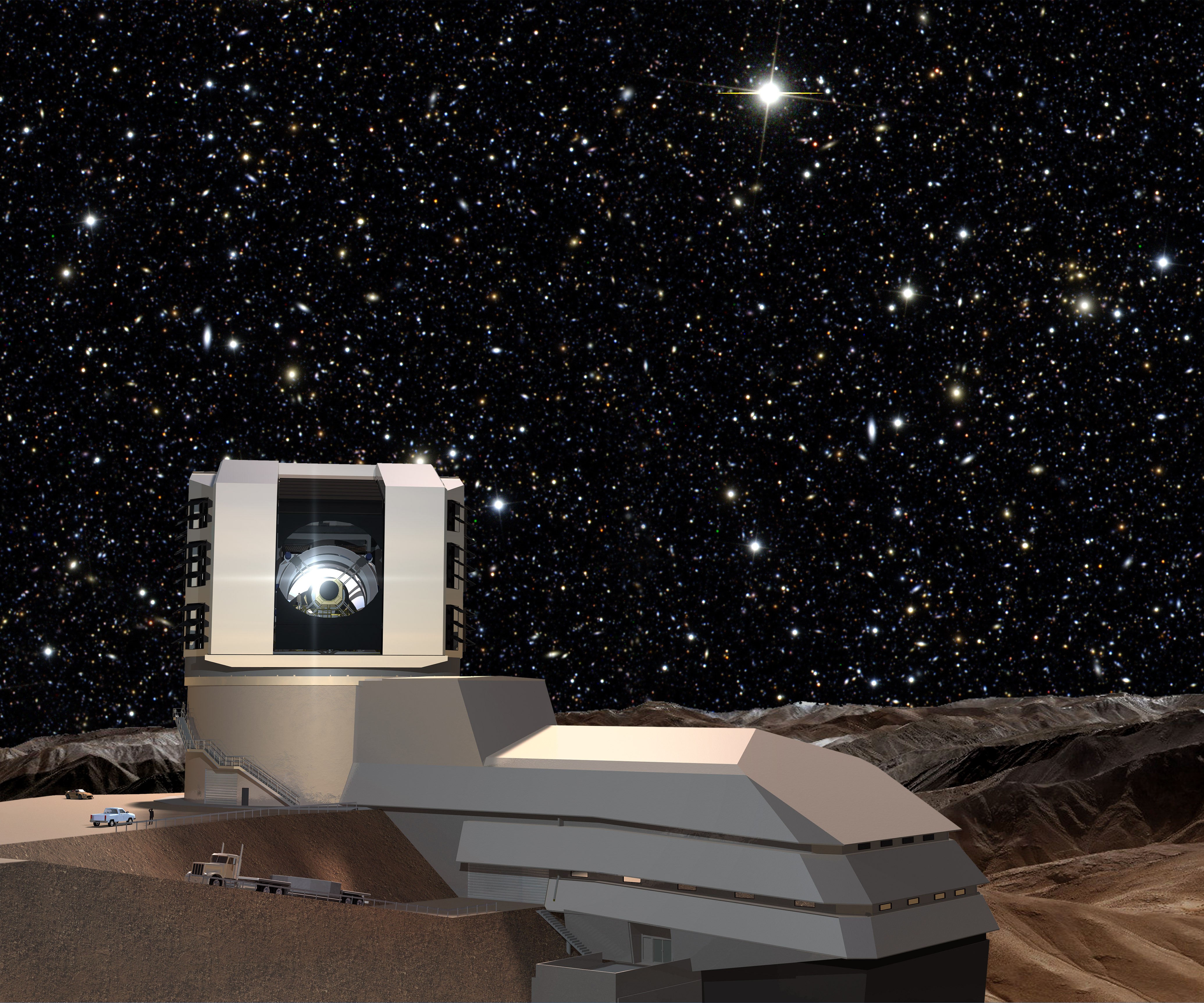
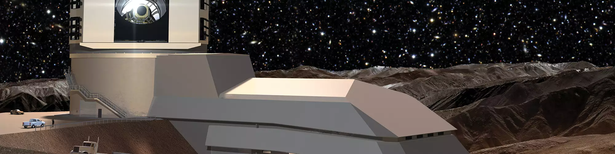
This artist’s rendering shows the Large Synoptic Survey Telescope (LSST) and its facility as it will look once completed. The telescope will be able to survey the entire southern sky once every other night, and capture what it sees with the world’s largest digital camera. Image: LSST Project/NSF/AURA
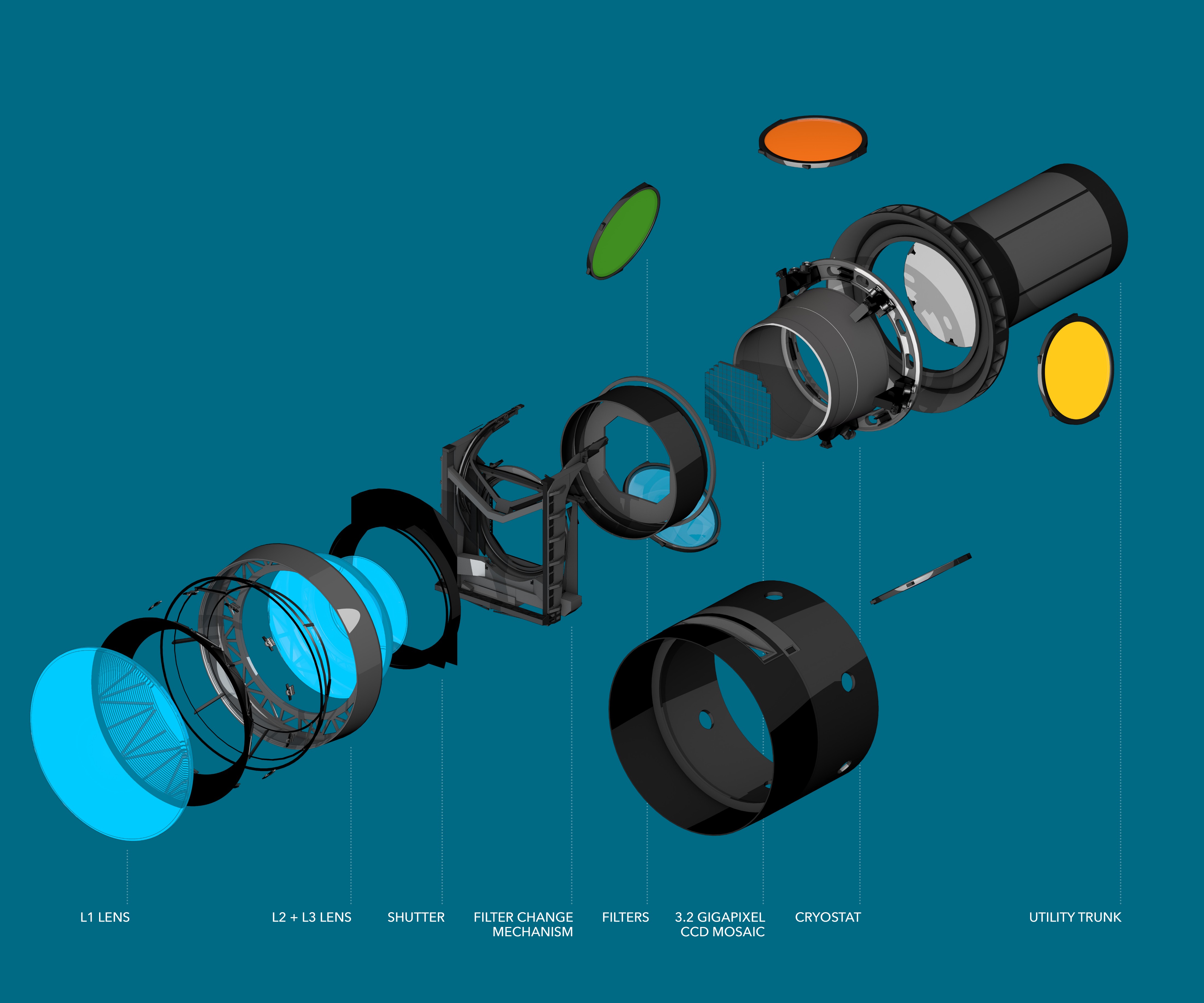
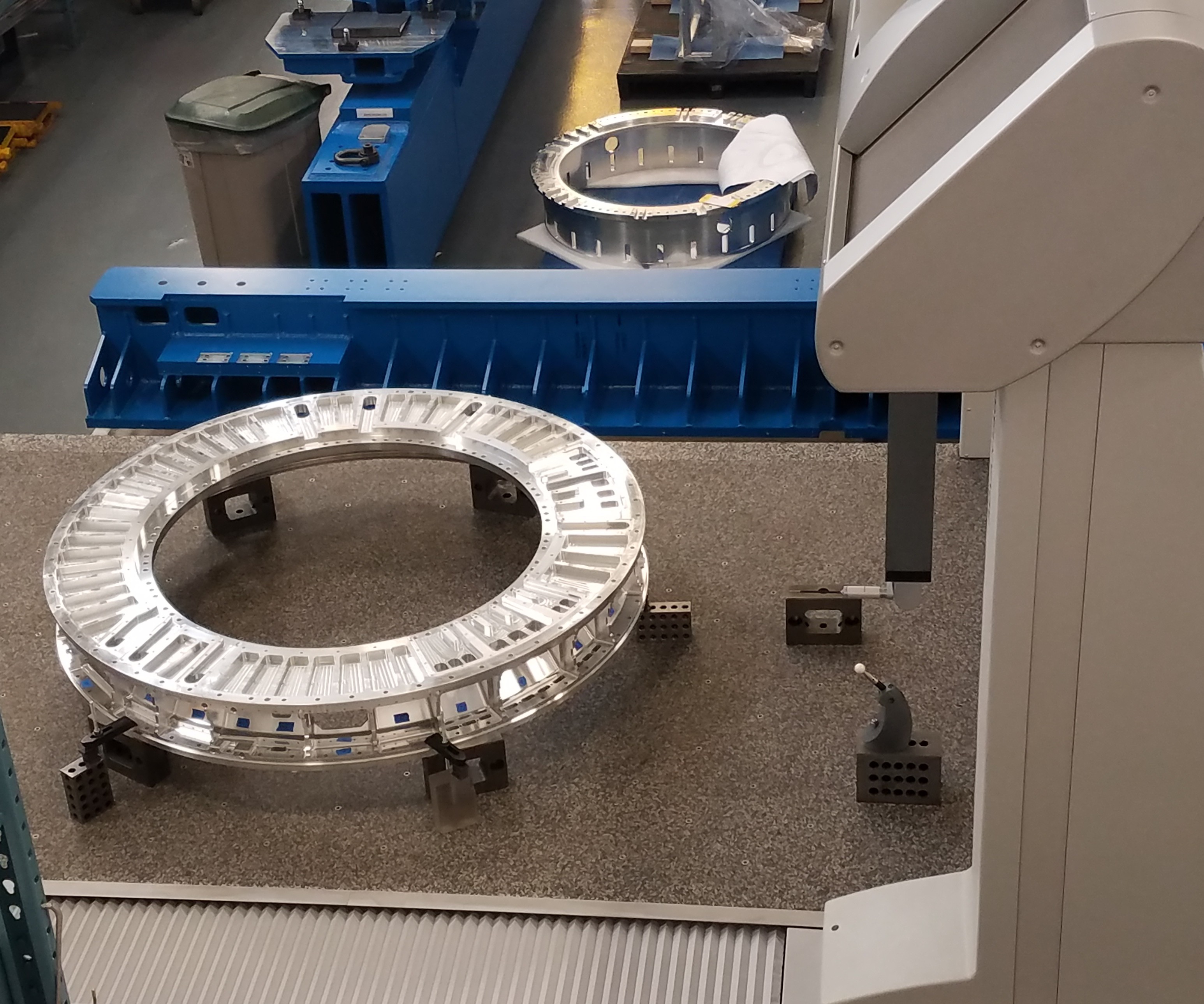
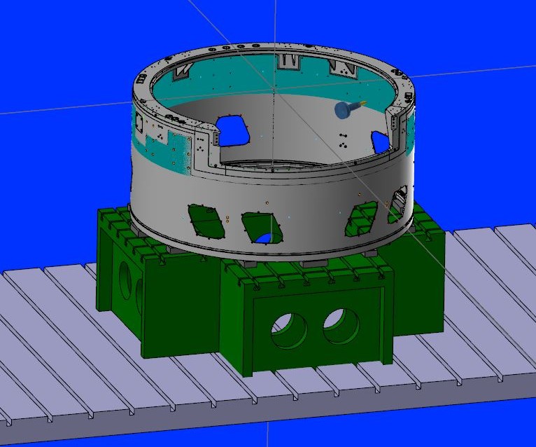
The LSST digital camera consists of a number of subsystems that are delivered to SLAC for testing and integration. The parts that Keller Technology machined for the project—the camera housing shown at the bottom of this graphic and the back flange connected to the utility trunk—will serve to protect and support the overall camera within the telescope. Image: SLAC National Accelerator Laboratory
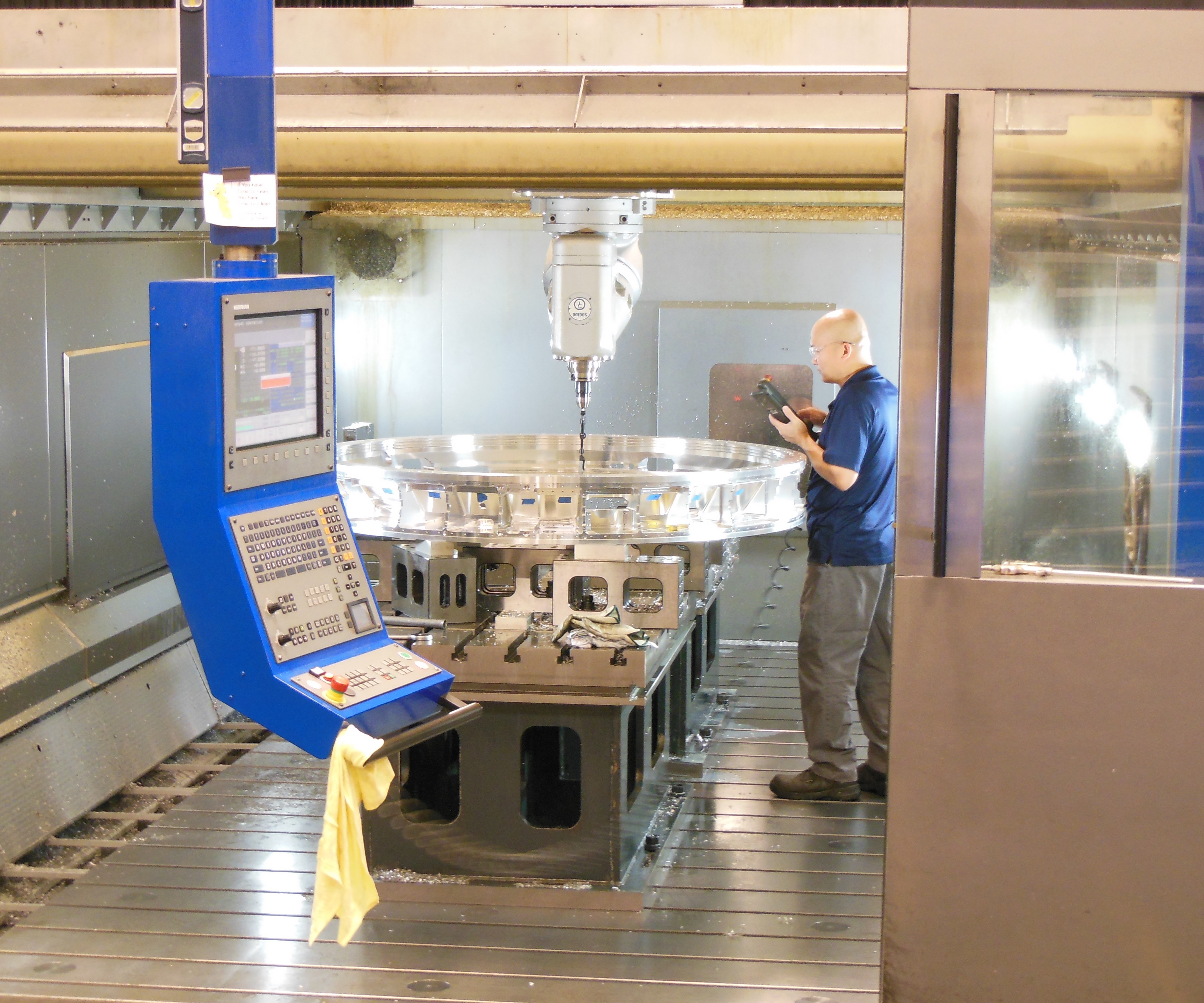
The gantry-style design and large work envelope of the Parpas XS 63, coupled with the flexibility of the five-axis high-speed milling head, made it possible to machine the flange in just two setups. Elevating the part above the table with a combination of precision blocks enabled maximum machining access. Standard clamps (not pictured) held the part in place. Photo: Keller Technology

The LSST camera’s back flange measures 1.65 meters in diameter and will serve as the interface between the camera and the rest of the telescope. Shrink-fit tooling plus a very light depth of cut enabled Keller to reduce vibration and improve accuracy in machining both the back flange and camera housing. Photo: Keller Technology
To inspect the back flange, Keller used both the touch-probing and scanning capabilities of its Global Advantage CMM. The company also had an added resource during this step: representatives from SLAC were present during the inspection of the part. SLAC partnering with Keller Technology allowed for clarification and adjustment of tolerances on the fly. Photo: Keller Technology
When the camera housing came back from stress relief out of round, Keller Technology set it up on its Toshiba Shibaura BF-130B horizontal milling and boring machine for probing to identify and mark which areas were out of spec and by how much. Determining the condition of the wall thickness in relationship to the final specification allowed Keller to adjust its manufacturing plan to produce an acceptable product for SLAC.
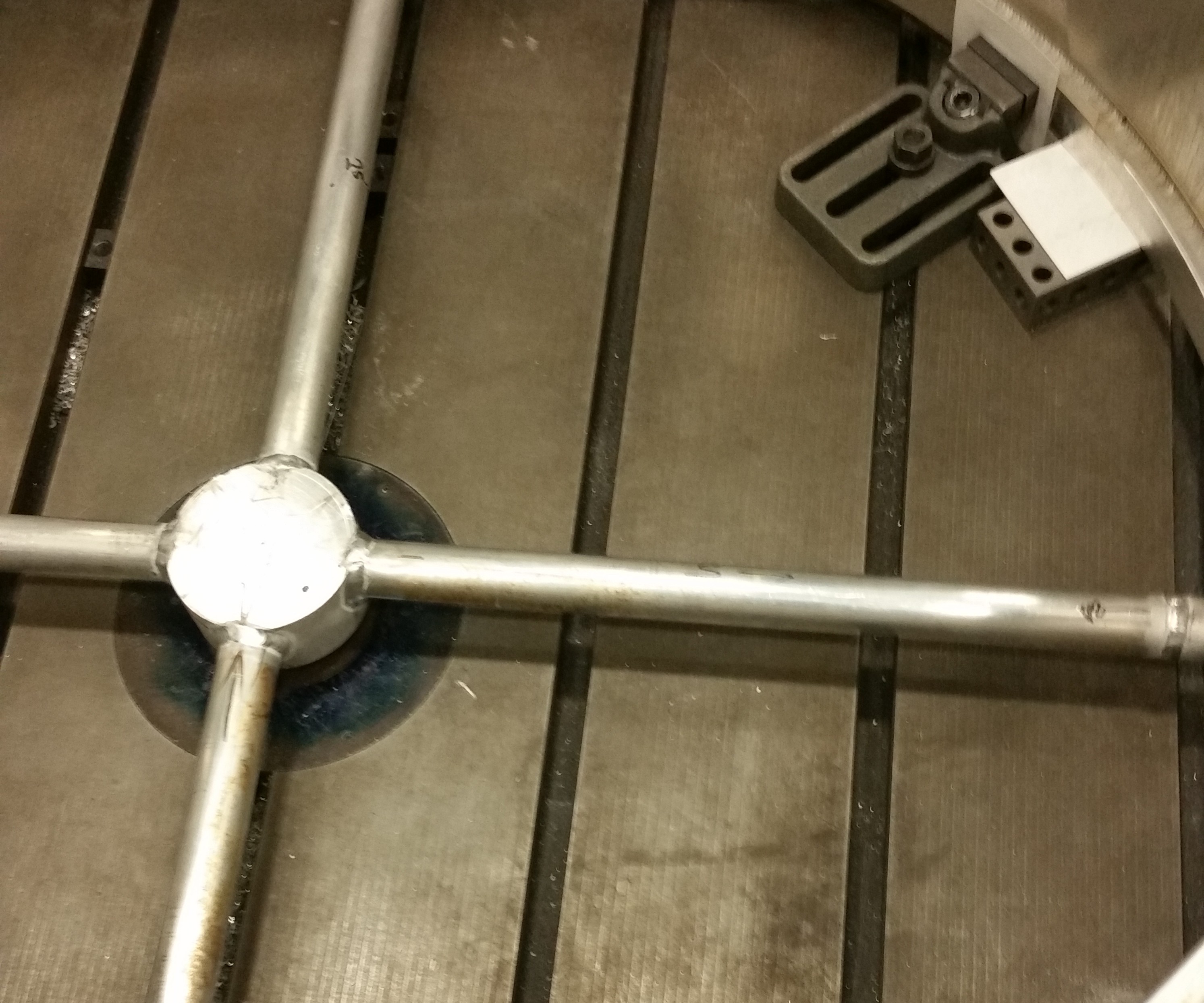
After jacking the camera housing out to the correct dimensions, Keller welded in two “spiders” like this to hold it in place. The whole assembly was sent out for stress relief together to keep the part round. Photo: Keller Technology
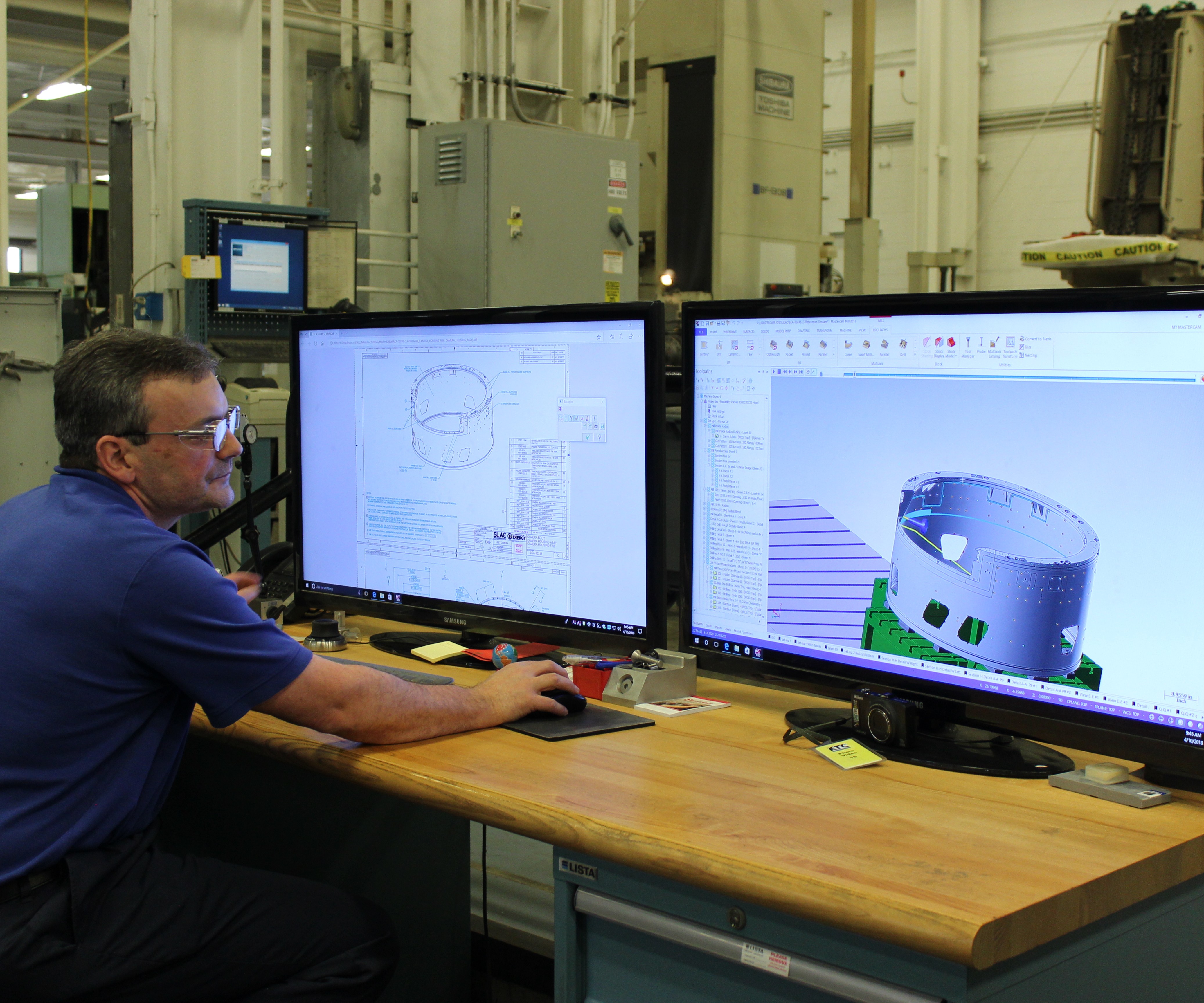
One advantage to Mastercam’s software is that it allows for offline work, so Scott Steggs, CAD/CAM manufacturing engineer, was able to program the camera housing while the Parpas ran other parts.
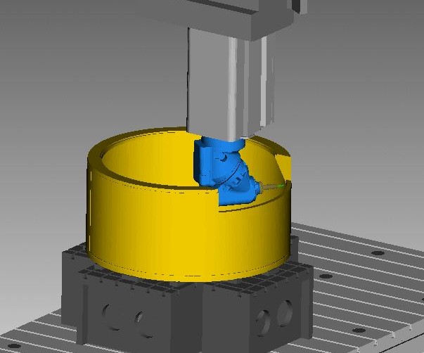
The gussets inside the camera housing mean that the upper half of the part cannot be turned, and will need to be milled from the inside with the Parpas using the high-speed milling head. Photo: Keller Technology
Keller uses Vericut to simulate and optimize tool paths, enabling the shop to run many jobs, even one-offs such as the camera parts, lights out. Photo: Keller Technology
After the camera housing returned from stress relief the second time, Keller removed the spiders and set up the part to be machined on the Parpas XS 63. The housing will be finished and shipped to SLAC later this year. Photo: Keller Technology


“A large fraction of the energy in the universe can’t be explained just by what we can see with a normal telescope,” Martin Nordby says. “There was a scientific need for an instrument like this to really better understand the nature of dark energy and dark matter.”
The instrument he is describing, the one that will widen scientists’ view of the universe, is the Large Synoptic Survey Telescope (LSST), which one day will be installed on a mountain top in Chile. This telescope will be able to survey the southern sky “almost horizon to horizon,” he says. But the LSST is not just for seeing the sky: It will also record it. Equipped with a massive digital camera, the telescope will enable scientists to photograph the southern sky every other night, and tile the pictures together to study how dark energy and dark matter interact with visible objects such as stars.


Mr. Nordby is the chief mechanical officer for the LSST digital camera at SLAC National Accelerator Laboratory (formerly Stanford Linear Accelerator Center), a federally funded lab in California that is one of the collaborators on this project. SLAC is responsible for designing and fabricating the digital camera for the LSST, said to be the largest digital camera ever constructed. Unlike other telescope cameras, which are typically plug-and-play units that can be swapped out with other instruments, the LSST camera is intended to stay put.
“Ours is really designed as a complete system,” Mr. Nordby says. The benefit to the built-in camera, he says, is that the LSST should have reduced systematic errors compared to other telescopes. But it’s also more challenging to design, build and integrate. The camera will be cantilevered into the middle of the telescope, so access is limited and repairs to the camera might mean significant downtime for the telescope. As such, Mr. Nordby emphasizes the need for high reliability in its components, which translates directly into manufacturing challenges in building them.
The Vision
Led by the LSST Corp., the telescope project began in 2007 with initial proposals and R&D work. Now, the project is nearing its conclusion. SLAC is one of many public and private collaborators, whose ranks include the Association of Universities for Research in Astronomy (AURA) and various laboratories worldwide. The National Science Foundation (NSF) is funding the telescope and data management system, and the Department of Energy’s Office of Science is funding the camera directly.
SLAC researchers in California have spent the past 10 years designing and engineering a complex, 3.2 gigapixel digital camera capable of capturing what the LSST will see. The camera consists of modules containing subsystems such as its shutter, a focal plane made of charge-coupled device (CCD) sensors, a cryostat to keep these sensors cool and a filter-changing system, among others. The modules are tested at the lab as they are completed and verified throughout the integration process.
Around all these subsystems will be an even larger aluminum structure, forming a complete camera weighing 6,200 pounds (2,800 kg). Parts of this outer structure—the camera housing and back flange—were recently manufactured in Buffalo, New York, by Keller Technology. These large pieces, both approximately 1.65 meters (about 5 feet, 5 inches) in diameter, nonetheless demanded tolerances within about 50 microns in critical areas to support the high-precision demands of the camera’s operation.
Looking Back…
Founded in 1918, Keller Technology is a family-owned business celebrating its 100th anniversary this year. Currently under the fifth generation of family leadership, the company occupies two facilities, one in Buffalo where the camera parts were fabricated and machined, and a second location in Charlotte, North Carolina. About 135 employees work in Buffalo, and another 65 in Charlotte.
Keller’s capabilities cover manual and robotic welding, machining, and assembly of systems for the semiconductor industry as well as national labs, medical equipment and general industry. One of its specialties is the manufacture of vacuum chambers, typically made from aluminum, that involve the use of its welding, machining and polishing capabilities, as well as in-house vacuum-testing equipment.
The shop prides itself on its ability to handle challenging, difficult and tricky parts. “I like to tell new people that everything here is here because other companies would struggle to do the work,” says Scott Steggs, CAD/CAM manufacturing engineer.
Keller has become adept at one-off and small-run projects, but for the past 15 years or so, the company has been moving toward more low-volume production work in its machining operations. “Longer-run projects give us an opportunity to improve our manufacturing process and get better at predicting and planning for future projects,” says Shane Slack, director of manufacturing. Knowledge gained can then be applied to future work.
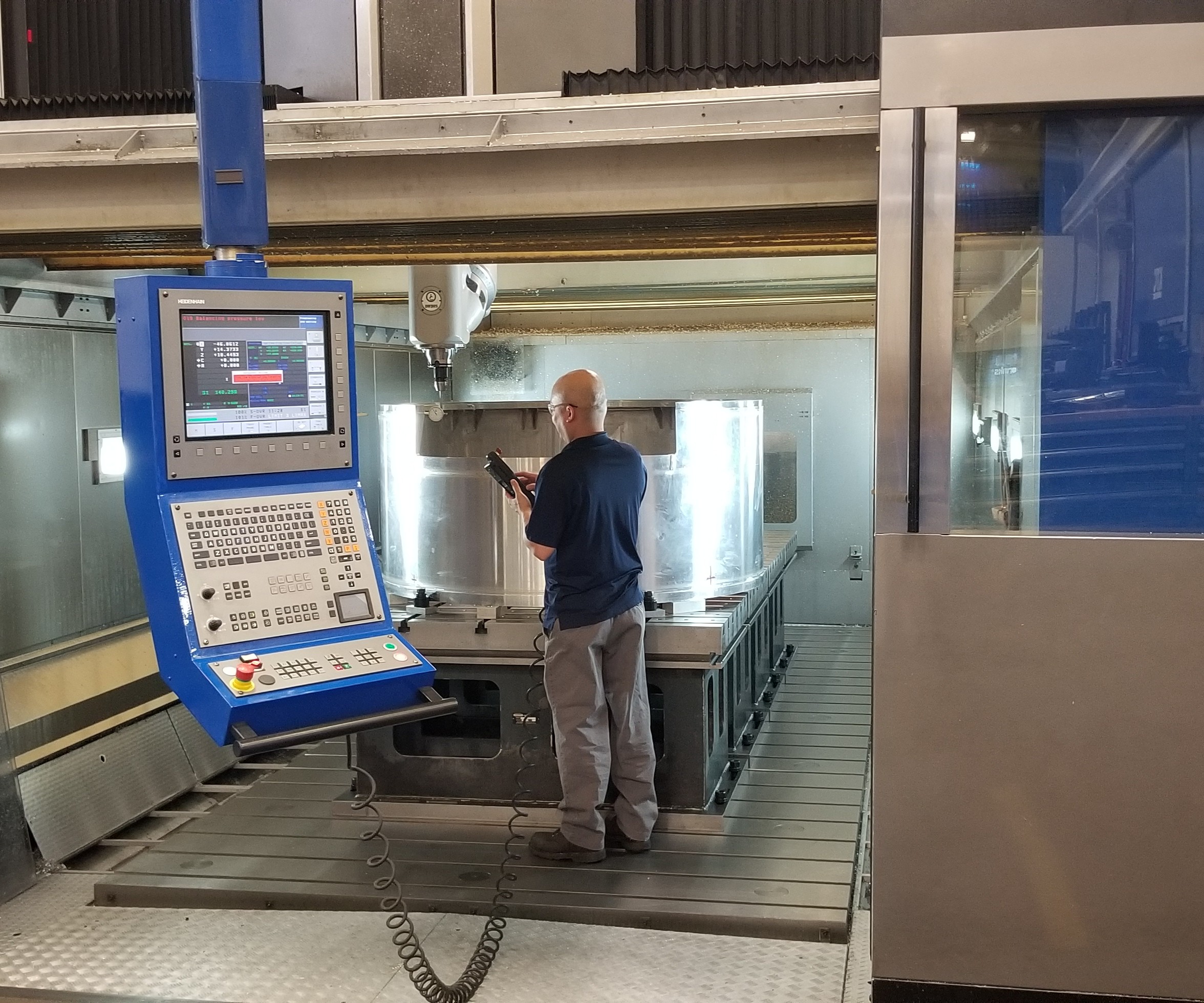
One way this knowledge building plays out is in a new emphasis on running parts, even one-offs, unattended. “We like to challenge ourselves to run lights-out any time we can,” Mr. Slack says. Keller’s newest machining center, a DMC 160 five-axis from DMG MORI, for instance routinely runs 60-plus hours unattended over weekends with success. Getting it right the first—and maybe only—time is critical. The planning and experience it takes to do this and adjust when things go wrong have become especially important on the large parts needed for the LSST camera.
…To Look Forward
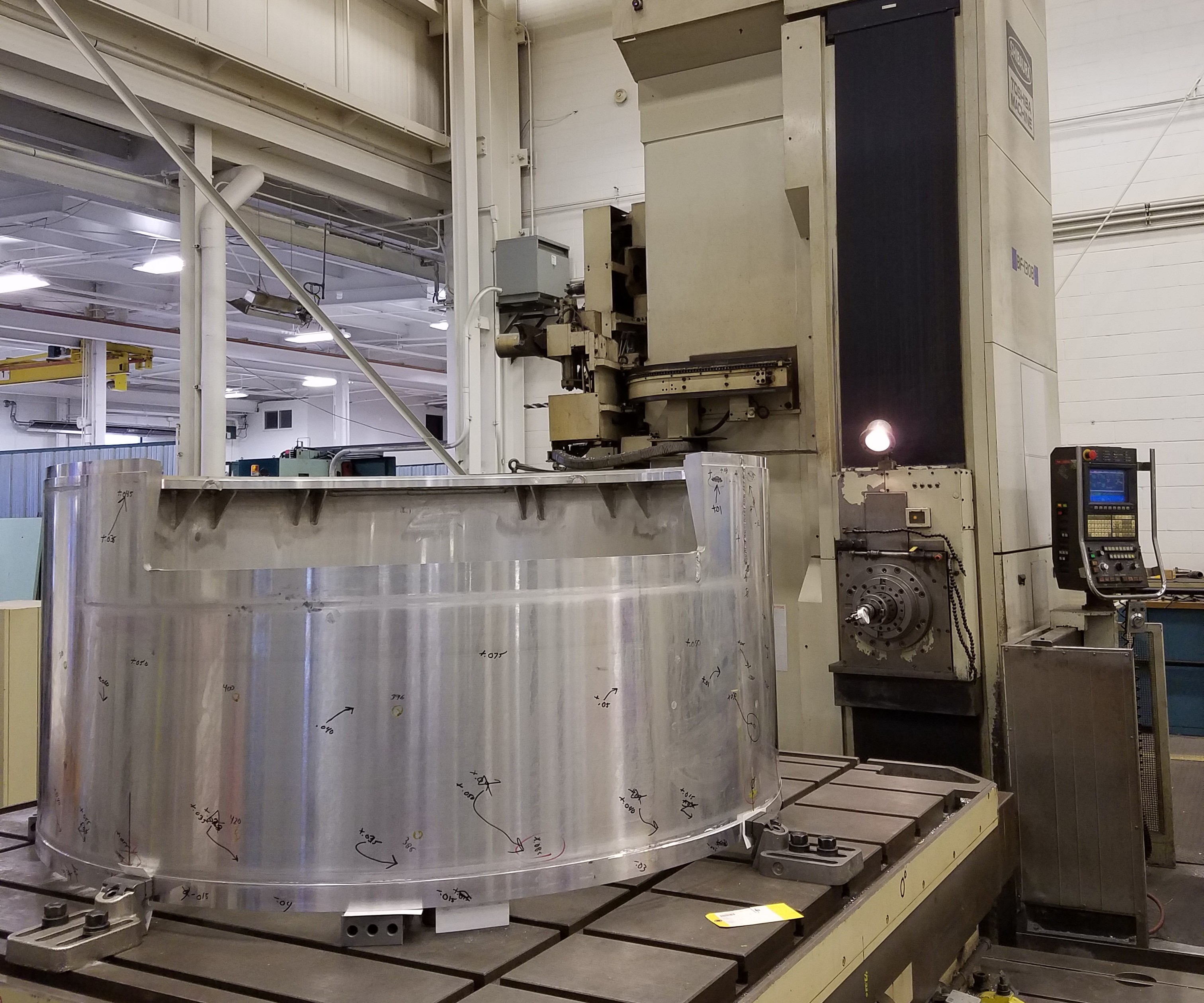
Keller has had to draw on its knowledge of welding and stress relief as well as machining expertise in manufacturing the LSST camera parts. When I visited in early April, the company had already shipped the back flange and was in the midst of producing the camera housing. The back flange is a flat, cylindrical part that provides structural support for the rest of the camera and serves as the mechanical interface between the camera and telescope. Made from a 6061 aluminum forging, the part was subject to vibratory stress relief before any machining to stabilize the atoms in the metal. Then, Keller cut the various holes and pockets on its Parpas XS 63 five-axis gantry machining center.
This machining center offers a large working envelope with X-, Y- and Z-axis travels measuring 236 by 118 by 59 inches, plenty of space to accommodate the 1.65-meter-diameter flange and housing, the latter of which measures 30.435 inches tall. However, the real benefit to this machining center is its exchangeable heads. Keller has three options: a roughing straight milling head, a universal indexing right-angle head, and a universal five-axis high-speed milling head. For one-off and low-volume jobs, having these options provides the flexibility to perform a range of operations on the Parpas with a limited number of setups.
For both the flange and housing, Keller used the high-speed head, which features an HSK 100 spindle interface and offers up to 20,000 rpm. The head’s small size means that it can fit inside these large parts to machine difficult-to-reach areas such as the pockets in the back flange. Shrink-fit tooling supported the long tools necessary to reach some of the pockets, and Keller milled with a very light depth of cut to ensure good surface finishes in these areas. The shrink-fit tooling also reduced vibration, resulting in more accurate and smooth cutting.
A workholding scheme that held the flange up off the table (using a combination of standard clamps with blocks and aluminum cutoffs from waterjetting to hold and elevate the part) allowed for better machining access. This arrangement plus the flexibility of the five-axis head made it possible to machine the back flange in just two setups. The company may use a similar strategy for the camera housing, where the ram and spindle will be inside the part to machine internal features.
To program the camera parts for the Parpas machining center, Keller started with Mastercam from CNC Software Inc. “There are a couple hundred operations on these parts,” says Mr. Steggs, who programed both LSST parts for the machining center. “It takes prep time to make sure we’re good out of the gate, and Mastercam is really our first line of defense not just for lights-out, but also successfully completing one-off or first-article jobs,” he notes. Once the program is created and initial simulations are run, Mr. Steggs moves to Vericut from CGTech for a comprehensive simulation of the toolpath motion and material removal process, including the guards, spindle, tools, clamps and fixtures. For complex parts such as the camera housing in which the spindle will need to operate deep within its inner diameter (ID), achieving an accurate simulation is especially important. Keller has also found that verifying dimensional accuracy and optimizing the tool paths in advance leads to better finishes on surfaces and edges.
Close Up
After machining, both parts require polishing to a No. 4 dairy, or sanitary, finish. This standard is commonly used in the food industry (including dairy equipment) because the surface created resists harboring potentially dangerous bacteria. Polishing is a core competency at Keller, because many of the vacuum chambers it makes require polishing around the seals. The slightest crosshatch can create a void and allow leakage, so it is crucial to get this step right. On the camera parts, dual-action (DA) polishers and Scotchbrite pads bring the finish to the required standard.
Despite their large size, the camera parts must hold to tight tolerances—within 50 microns, in some critical dimensions. For both camera parts, Keller is using a Global Advantage coordinate measuring machine (CMM), a large-envelope system with measuring range of 2,000 by 4,000 by 1,500 mm accurate to within 0.0005 inch. The CMM is programmable and motor-driven, and can scan parts as well as touch-probe them. The scanning capability is especially helpful for complex parts like these, says Steve Krengulec, quality control inspector. “Scanning gives us a profile—a location plus flatness—and it’s one of the best geometric dimensioning and tolerancing metrics to use,” he says. The scanning capability provides a more complete picture of each part and is able to map that data onto the CAD model showing any areas that are out of tolerance as well as the nominals for what the dimensions should be. It is also much faster than collecting manual points. PC-DMIS software captures the data collected by the Global Advantage CMM.
For the camera flange, Keller also had an added reference: the customer. Representatives from SLAC were actually present in Buffalo when the shop was inspecting the machined and polished flange. The intricacy of the part and its many features still made inspection a tedious process, taking three or four days, Mr. Krengulec says, but having the customers there brought major time savings. SLAC engineers could help interpret drawings, clarify which dimensions were critical, answer questions and come to an agreement on what to do when any dimensions were out of tolerance—a negotiation process that would typically have to happen over the phone or through email. The team actually discovered that some of the set tolerances were too difficult to achieve, and SLAC lessened the requirements on the spot. “On our end, we’re not waiting for answers,” Mr. Krengulec says, “while on their end, they’re getting faster delivery.”
The flange then went out for Alodine plating and returned to Keller, where threaded inserts were added. This step was particularly challenging because it had to be done without damaging the plating, so staff wore gloves and used padding to prevent scratches to the part. The inserts were installed while the part sat on sawhorses with one employee standing inside while another assisted from the outside. Every threaded insert was inspected after installation. The flange arrived at SLAC earlier this year to receive purge-line parts and covers, after which it will be shipped to an LSST partner in France for integration with the camera’s filter-exchange carousel.
Refocus
While the camera parts share characteristics with the vacuum chambers and other large welded pieces Keller commonly manufacturers, not everything has gone smoothly. The company has had its hang-ups with these parts, but is applying the same flexibility and learning attitude to the back flange and camera housing that it would on any other job.
While the back flange was completed by the time I visited Keller, the camera housing was still underway and proving to be even more challenging. The housing is a cylindrical 6061 aluminum part the same diameter as the back flange (5.5 feet), but taller (about 2.5 feet high) and with thinner walls. The housing is actually several pieces welded together; the main shell is rolled metal, with forged rings on the top and bottom. Additional side plates are welded in several places, as are gussets all the way around on the inside.
Keller performed the welding in house, then sent the part out for initial OD/ID turning on a large vertical turning lathe. That is where the trouble started. The shell, which had a starting thickness of 0.625 inch, needed to be finished down to 0.25 inch or less in some places. Welding causes residual stresses in metal, and as the housing got thinner, those stresses began to show themselves. “We thought we had plenty of material to machine,” says Jorge Martinez, quality department manager, but the wall became so thin that even handling it could make it go out of spec, and the subcontractor halted the operation. At that point, Keller sent the housing out for a low-temperature thermal treatment, a controlled process in which metal is heated and cooled gradually to relieve stress while limiting the effect on the aluminum-base-metal properties. The company hoped this process would help stabilize the welded material, but the housing came back from stress relief out of round.
To counter the roundness issues, Keller set up the camera housing on its Toshiba Shibaura BF-130B horizontal milling and boring machine. The idea was not to use this machine tool for cutting the part, but rather, to use the Toshiba’s large turntable to facilitate on-machine probing to determine where the part was out-of-round and by how much. The machine’s open architecture also enabled access for another step: welding.
When I visited, the shop was in the process of mechanically straightening the part. “We jacked it out (like you would with a car jack) until it reached the correct dimensions,” Mr. Martinez says. Then, the company fabricated a four-spoke support structure from aluminum tubing. This support, called the “spider,” was welded inside the camera housing while it sat fixtured on the Toshiba. A second spider was about to be installed at the time of my visit. The housing then went out for thermal stress relief again, this time with the spiders in place to keep it round, and at a higher temperature to ensure removal of internal stresses.
Approaching the Big Picture
Once the housing returned from stress relief for the second time, Keller removed the spiders and sent it out for turning. The next steps will be to machine the cutouts and finish it on the Parpas gantry machining center. Programmer Scott Steggs already has a CAM program in progress for the part; one benefit to the Mastercam software is that it allows for offline work, so that Mr. Steggs can work on the camera-housing part while other parts are running in the machining center. By the time the part came back from turning, a CAM program was ready and verified through the Vericut simulation software.
“Finishing inside the part will be challenging,” he says, because the housing requires surfacing to remove stock between 0.125 and 0.1875 of an inch throughout. Keller will again rely on the high-speed machining head, not just for its speed, but also its size: The gussets on the housing’s inner diameter make it so that only about half the interior can be turned by the subcontractor, so the rest will need to be milled on the Parpas with the head inside the part. The internal radius will be machined with a ball mill with stepovers of around 0.03 inch. Openings will also need to be cut and holes drilled before machining is complete. The camera housing will go through polishing and inspection before delivery to SLAC later this year.
While the process for manufacturing these parts has not been easy, “I like to think one reason they [SLAC] came to us is that we have the ability to deal with complicated, challenging parts,” Mr. Slack says. That means not just having the machining capacity to make parts like the camera housing and back flange, but also the flexibility and creativity to deal with problems as they arise. It also means learning from every part that comes through.
“Now on something similar to the camera housing, we know what the aluminum wants to do.”
“Now on something similar to the camera housing, we know what the aluminum wants to do,” Mr. Martinez says. “We know that roundness is difficult to achieve with a welded construction like this,” he explains, saying that the company would use a different weld preparation and different stress-relief conditions on any future parts resembling this housing.
The work that Keller Technology and other contractors involved in this project have contributed to the LSST components may very soon pay off. Back at the lab, “We’re about two-thirds of the way through fabrication right now,” Mr. Nordby says. Delivery of the camera to the summit in Chile is expected in May of 2020; once in place, it will allow scientists to study everything from near-earth asteroids to the very oldest parts of the universe. “We’re expecting and hoping to make great discoveries.”


Related Content

YCM Alliance Hits IMTS
YCM Technology has joined with other like-minded machine tool manufacturers to take a solutions-based approach to manufacturing.
Read More
How to Accelerate Robotic Deburring & Automated Material Removal
Pairing automation with air-driven motors that push cutting tool speeds up to 65,000 RPM with no duty cycle can dramatically improve throughput and improve finishing.
Read MoreRead Next


3 Mistakes That Cause CNC Programs to Fail
Despite enhancements to manufacturing technology, there are still issues today that can cause programs to fail. These failures can cause lost time, scrapped parts, damaged machines and even injured operators.
Read More
The Cut Scene: The Finer Details of Large-Format Machining
Small details and features can have an outsized impact on large parts, such as Barbco’s collapsible utility drill head.
Read More