
Making Sense Of Model Data
Designs often arrive incomplete downstream. There may be no changing that. But these tools can reduce the amount of time spent on reworking customer models.
Share


Phillips Corporation - Education
Featured Content
View More


Phillips Corporation
Featured Content
View More

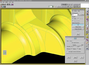
The transform mode lets the user merge surfaces to create a smoother model.
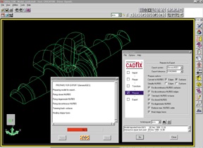
In the prepare mode, the software formats the model for the system that will use it next.
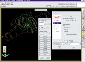
In the repair mode, the software mends disconnected features of the model.
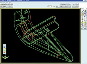
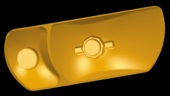
This image, and the images to follow, all come from a stand-alone software utility for CAD model repair. The model shown here has just been imported into the software. The red lines show where faces of the model are not joined, and therefore in need of repair. (Images courtesy ITI.).
The Web site called 3Dmodelserver performs CAD model healing. Users upload their models via an interface like this one.
The healing site takes about an hour to do its work. Users can check the status of models in process.

A model that looks continuous and watertight may in fact be riddled with discontinuities. These gaps often result when a CAD model created in one system is translated for another system’s use. The images here are courtesy Delcam, which engineered its CAD/CAM software to tolerate gaps like these appearing in outside models that are defined using IGES and other formats.
A model that looks continuous and watertight may in fact be riddled with discontinuities. These gaps often result when a CAD model created in one system is translated for another system’s use. The images here are courtesy Delcam, which engineered its CAD/CAM software to tolerate gaps like these appearing in outside models that are defined using IGES and other formats.
As contract shops that machine molds, dies, aircraft components, and other complex parts can attest, the devil is in the details. More powerful CAD and CAM systems have made it possible for designers to design, and shops to machine, increasingly complex parts. But between CAD and CAM, the complexity causes problems. Features of the model that seemed elegantly joined as far as the original CAD system was concerned now come undone in the downstream software. When upstream CAD and downstream CAD/CAM systems are unrelated, and when these systems therefore must exchange data for a complex model via the neutral IGES format (to give a common example), such gaps and discontinuities frequently creep in.
There is, of course, an infamous answer to this problem. Customers who purchase machining work often mandate that their suppliers use software from the same “suite” as the customer’s own system, to eliminate the need for the model data to be converted. However, this approach has problems of its own. It eliminates from competition all suppliers who do not purchase the mandated software. It also adds the cost of this software to the overhead that suppliers must recoup. But most significant of all, applying such a mandate in the realm of smaller contractors and farther removed “tiers” is simply impractical. Contract mold shops, for example, often must work with complex models from many different customers using many different systems. As a result, these shops accept it as a given that files from customers will arrive in varying degrees of imperfection, and that the shop’s programmers will spend some of their time manually fixing these models.


And ultimately, there is no substitute. No expert system yet developed is “intuitive” enough to take the place of an experienced programmer at interpreting all the potential imperfections in a complex design file.
However, there are tools that can help. There are resources available that can at least reduce the amount of time the programmer must devote to this work. Some of these resources have become widely available only in the last year or two.
One resource that stands out is a Web site. If a model suffers from gaps between entities—that is, gaps large enough that they must be closed in order for the CAM system to use the model effectively—then the file can be uploaded to www.3Dmodelserver.com for automatic “healing” of at least some of the file. The cost to the user is based on the extent to which the model was mended.
A more interactive resource is a software utility called Cadfix. This software (available from ITI Tooling of Milford, Ohio) translates between a variety of CAD formats, and along the way, locates imperfections in the model and presents the user with options for fixing them. Thus the software acts like a “spell checker” for models.
But to round out any discussion of working with foreign CAD files in a supplier’s system, it’s important to note that the downstream system itself may be able to overcome the need for utilities like the two just described. Different systems offer different levels of sophistication at working with potentially incomplete model data. Some CAD/CAM systems have healing capability built in. Others may feature deeply integrated functionality that lets them interpret the model correctly despite some discontinuities, freeing the user from having to worry about fixing small flaws.
In other words, the supplemental utilities can help the programmer use an existing CAD/CAM system more productively. But when shopping for a new system, how well it works with models in various states of “disrepair” may merit careful consideration.
What this all means is that there is a variety of alternatives for addressing the problem of model information being lost in the conversion from one CAD format to the next. This article discusses the alternatives mentioned above, starting with the Web.
e-Healing
Spatial Technology (Boulder, Colorado) developed the site. It relies on healing technology that is available to software developers who use Spatial’s ACIS solid modeling kernel. The site converts files to the ACIS SAT format to perform this healing. At this writing, users can input IGES, SAT, STEP, or CATIA files, and the healed files can come back in either IGES or SAT format. Turnaround time is generally less than an hour, not including upload and download time.
Whether in a CAD/CAM system or on this site, the healing process involves mathematically redefining a model so that the boundaries at which its surfaces or faces intersect more closely match one another. When unacceptable gaps appear or seem to appear in the model, part of the cause can be attributed to boundary lines not matching one another closely enough for the CAD/CAM system to understand that the two lines are actually meant to be one continuous seam between surfaces. It may be that the original CAD system permits a “looser” match than the software downstream, so the latter system finds a gap where the former inferred smooth closure. However, the conversion to IGES may also contribute to the problem. In IGES, topology information is lost that describes how surfaces are linked. In addition, depending on the specific IGES translation algorithm used, IGES itself may redefine the model in terms of a looser edge tolerance than was used in the model’s creation.
Healing is not a perfect process for mending these imperfect models. Spatial stresses that neither the Web site nor healing in general should be expected to correct all of a model’s gaps. At best, the technology is an aid that reduces the amount of time a human has to devote to this work.
In the case of the Web site, pricing is based on how much healing did occur. The site looks at the percentage of the original model’s data that was represented by intersections in need of healing, and compares this to the percentage still in need of healing once the process is done. The cost to the customer is based on the difference.
Tolerant Modeling
The precise definition of model “healing” varies between software companies. However, healing, in general, refers to redefining the model in an effort to make it as continuous and watertight as possible. Healing is one fundamental response to the problem of how to minimize the time a programmer must spend on reworking models. But it’s not the only such response. Another is “tolerant modeling,” which makes the CAD/CAM system itself more forgiving when there are gaps of various sizes in the model. Tolerant modeling is either a complement or an alternative to healing, depending on the perspective of the software developer.
Tolerant modeling functionality expands a CAD/CAM system’s ability to infer the correct design intent from model data. It accomplishes this by expanding the tolerance bands around surface boundary lines. Surfaces are then treated as joined and continuous if their boundaries match within these bands. Whatever gaps exist in the model continue to exist, but the software is nevertheless able to deduce the correct tool paths to machine the form that the designer had in mind. Thus, tolerant modeling has a double meaning. Strategically affecting tolerances makes the software more tolerant.
Many CAD/CAM systems feature both healing and tolerant modeling capabilities. Healing closes many of the gaps in the model, and tolerant modeling helps the software correctly interpret much of the rest.
At least one software company takes a different approach. Delcam (Windsor, Ontario, Canada), a maker of software for the relatively narrow user group of mold makers, die makers, and others concerned with machining complex shapes, developed its software to rely solely on tolerant modeling for interpreting models from outside, without any preliminary healing step.
This software is based on the company’s own modeling kernel. Because the company has always been focused on the problems related to complex surfaces, the need of users to be able to import and work with imperfect outside models has always been a concern. Tolerant modeling has been integrated into the kernel since early in the development of the company’s products.
But this is not to say that pure tolerant modeling is necessarily a superior approach to healing plus tolerant modeling. Even Delcam is careful to note that comparing these approaches, or comparing kernels, amounts to apples and oranges. Different kernels are applied more broadly. And when a kernel relies on close matches to determine when entities mate instead of wider tolerance bands, this can make the kernel faster and more efficient at modeling simpler forms. Healing and tolerant modeling capability added to the same kernel later can expand its capabilities into modeling more complex forms. However, Delcam developed its own kernel to rely on tolerant modeling from the beginning because it never saw the reliance on close matches as being the most practical approach for its intended user group— shops that work with complex forms routinely.
Error Checking
The stand-alone software utility, Cadfix, can be thought of as an aid for those downstream systems (CAM and otherwise) that are limited or lacking in the ability to repair and/or interpret foreign models. In addition, this utility is also meant to be a check against errors resulting from the designer leaving some detail incomplete. Complex designs make this variety of error more likely, too. And while many customers for machining work do have procedures for quality testing of design files before they are sent to suppliers, not all such companies have these controls in place.
Cadfix reads in files in formats including IGES, STEP, STL, ACIS SAT, CADDS 5, and Parasolid. The software carries the model through five sequential modes of operation: import, repair, transform, prepare, and export. In the repair mode, problem areas of the model are highlighted and the user is presented with options for fixing them. Tolerances that determine various types of “errors” can be adjusted here. The default tolerances themselves change, depending on the identity of the original CAD system (information that an IGES file does preserve). Different CAD systems use different tolerances, so different tolerances are necessary for determining, for example, when a given data point is redundant with another point.
The transform mode is an optional part of the sequence. In this mode, the model can be simplified by merging some surfaces to create a smoother model. Finally, the prepare mode prepares the data for the downstream system that will use it next. The software can export to the same formats listed above for importing.
The software works interactively. It still presumes that a human being will devote some of his time to reworking a model that may or may not have been perfectly intact before it left the designer. Neither this software nor any of the alternatives mentioned in this article, can promise to eliminate this chore.
However, what each of these alternatives potentially can do is to reduce the amount of time that has to be spent on this rework. In downstream shops, they can let programmers spend more of their time actually creating programs.


Related Content

Orthopedic Event Discusses Manufacturing Strategies
At the seminar, representatives from multiple companies discussed strategies for making orthopedic devices accurately and efficiently.
Read More
The Smarter Way to Take Full Control of Your CNC Machine Shop
Designed to bridge the gap between CAM programmers and shop floor operators, SolidShop provides a seamless, real-time solution for managing G-code, tracking production and eliminating costly mistakes.
Read More
10 Robotic Solutions You Can Find at IMTS 2026
Discover how today’s robots and cobots are making it easier than ever to automate tasks, free up skilled workers, and run machines unattended – even in small and midsized shops.
Read More
Continuous Improvement and New Functionality Are the Name of the Game
Mastercam 2025 incorporates big advancements and small — all based on customer feedback and the company’s commitment to keeping its signature product best in class.
Read MoreRead Next

WEBINAR: From Machine Data to Guided Action: How Modern Shops Are Closing the Execution Gap
In this webinar, MachineMetrics Product Manager Josh Fish is joined by Pindel Global Precision's Thomas Deslongchamps, for a candid look at what closing the execution gap actually looks like inside a precision machining shop.
Read More