The challenge has long been familiar: Every day a variety of parts, similar in size and shape, are manufactured, and they need to be inspected for conformance. What is different in today’s manufacturing environment is that long runs of the same parts are becoming rare. Short runs are far more prevalent. Therefore, flexibility is vital in today’s manufacturing environment.
This need for flexibility extends to part inspection as well. In a perfect world, a manufacturing process would be established and stabilized, and good parts would be produced like clockwork. Unfortunately, there is variation in any process and—depending on the process, value or critical nature of the parts—some method of inspection must be selected to ensure that parts meet specifications. Whether it’s a sampling check, critical dimension check or 100-percent inspection, a certain type of gaging will emerge as the most cost effective for the application.
Traditionally, selection of dimensional gaging systems has followed a rule of thumb that says the higher the production run, the more cost effective a dedicated or customized gaging system is likely to be; while the shorter the run, the greater the need for gaging flexibility and versatility. By this rule, a dedicated gage would be faster, more accurate and subject to less operator influence. Also, it likely would be more expensive, but because that cost could be amortized over a long production run, it ultimately would be more economical. A more general gaging system, on the other hand, would be less expensive and be able to measure a greater variety of parts and dimensions, but would require more complex setups and longer measuring cycles.
With short runs and quick change-overs becoming the norm, that rule might be less certain. No longer can the need for flexibility outweigh the need for speed, accuracy and low cost. Thus, modular systems are coming on the market to provide the best of both worlds: Systems feature components that offer the flexibility and versatility of a general gage, yet they can be combined to provide the speed and accuracy of a dedicated gaging fixture.
Such systems are not expected to replace traditional gages, but to add more options to the gaging paradigm. A look at some of the concepts behind these systems shows how they will augment existing measurement devices.
Traditional Gaging Options
There are many ways to measure ODs, IDs and lengths. The range includes calipers, micrometers, comparative gaging, CMMs and optical shaft systems. The choice depends on many factors, including throughput, ease of use, accuracy, cost and the measuring capabilities of various gage features.
• Calipers and micrometers. At the low-precision, high-flexibility end of the spectrum are handheld gages such as calipers and
micrometers. Both are extremely versatile and useful tools for making a wide range of distance measurements (both ODs and IDs). Of the two, the micrometer is more popular and offers a small step up in accuracy and performance—but with a shorter measuring range. However, both require time and operator skill for positioning
the tool and interpreting the measurement result. Although they can measure a wide range of
different parts, the accuracy of either instrument is ultimately determined by the skill of the
operator.
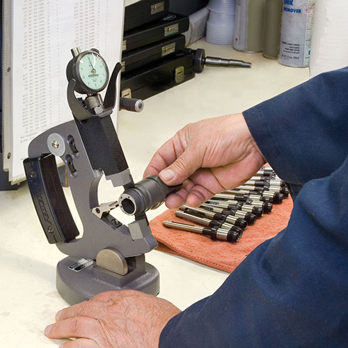
• Comparative gages. Once tolerances reach the 0.0005-inch level, a step up to comparative gages, such as bench stands, snap gages or ID/OD gages is required.
For example, when checking the shaft diameter on a part turned on a CNC lathe, a micrometer might be the instrument of choice, and it may be able to resolve to 0.00005-inch. The situation changes if the diameter must be checked at multiple locations to ensure the part is not tapered. In this instance, the operator brings the micrometer, gets it to nearly the right size, adjusts the torque to the correct gaging pressure, removes the micrometer to read the size and moves to the next inspection point. This repetitive process is inherently inefficient and results can be negatively influenced by the operator skill level. A better choice in this case is an adjustable snap gage.
The experience of inserting a snap gage onto a workpiece makes it apparent how these effective, yet fairly simple OD gages got their name. Once the part overcomes the “locking” spring tension, it suddenly slips against the backstop, contacting it with an unmistakable “snap.”
A snap gage can be held by hand to measure ODs while the workpiece is still on the machine, or it can be mounted on stands for use with small parts. The heart of the tool is a simple C-frame casting. Measurements are derived by a direct, in-line transfer of motion. This function makes a snap gage simple, reliable and fairly inexpensive.
Other benefits of using a snap gage are the speed of the measurement and the lack of operator influence. There is no need to adjust the gage to the right size, ensure that the gage is square to the part or apply the right force on the part. It’s all built into the gage. Thus, a snap gage is faster and more accurate than a micrometer or caliper.
• Custom fixtures. However, the benefits of using a snap gage are reduced if a shaft
has several diameters to be checked. While snap gages are adjustable in a size range, they can only measure within this limited range. In order to retain speed and accuracy when checking multiple diameters, multiple snap gages are needed. Each diameter requires another gage and additional time to make the check. For example, checking six diameters requires six gages and six separate measuring operations.
To improve measuring speed or part throughput, custom fixture gaging might be the best solution for these measurements. However, because these inspection devices are custom designed and produced, they are often expensive and not flexible enough to accommodate part variations going though a machining cell. Thus, the investment can be substantial if a custom gage is required for each part in production. In this case, a modular, flexible gaging system can be an attractive alternative.
The Modular Concept
The idea behind modular gaging fixtures is to take all the elements found in high-precision, comparative gaging and turn them into reconfigurable, modular components. Comparative gages consist of basic, common components. For example, comparative gages have solid reference anvils, a sensitive contact, part references (backstops) and a readout, all mounted on a stable frame.
The use of standard components enables flexible measuring devices to be designed and assembled for a wide range of workpieces. Common elements enable them to be recon-figured for similar or different applications. Whereas a traditional comparative gage might be built for one size shaft with five diameters, a modular gage can be adjusted with relative ease for five diameters of different sizes and at different locations.
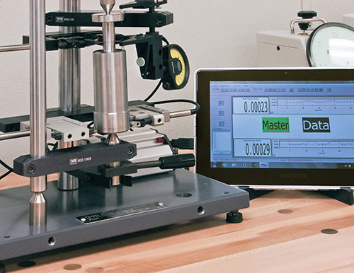
Along with the flexible gaging components, an instrumentation package—perhaps tablet based—is needed to store various programs corresponding to the parts to be measured. Thus, change-over involves reconfiguring the gage components for the next part and selecting the matching part program. This concept follows the strategy of using the same machine to produce similar parts by simply changing pre-set cutting tools and downloading the correct part program.
Thus, while the machine operator changes tooling and reprograms the machine for the new part, the gage technician resets the modular gaging elements to the new part and selects the correct gaging program.
Whether measuring an OD, ID or length, the modular gaging elements can be configured
for simple or complex workpiece geometries. Keeping the design of the modular components slim and compact, many measuring points can be inspected within a small area of the workpiece.
Just as there are different levels of performance and robustness in the design of standard, hand-held comparative gaging, modular gaging components can follow a similar design philosophy. For example, if the tolerance on the part is fairly “wide open,” a modular element with the appropriate level of precision can be applied. However, if the manufacturing process occurs in a harsh environment and involves tight tolerances, suitable modular elements and gaging techniques are available as well.
Optional Configurations
Let’s take a look at the components for “good, better, best” options for measuring an outside diameter.
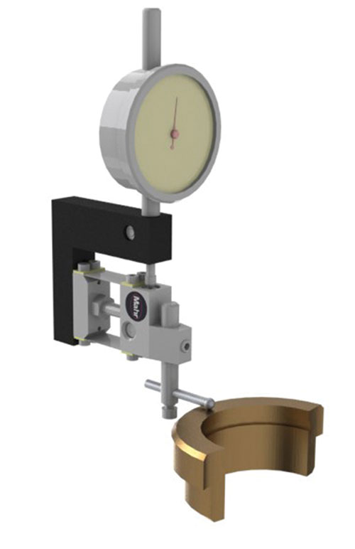
• Good. A single LVDT (linear variable differential transducer) or digital indicator and a set of parallelograms linked together as shown in the second illustration creates the least costly configuration that offers fairly good performance. It is likely to be sufficient for a simple dimensional check. Because the parallelograms are subject to little friction, they can provide years of service.
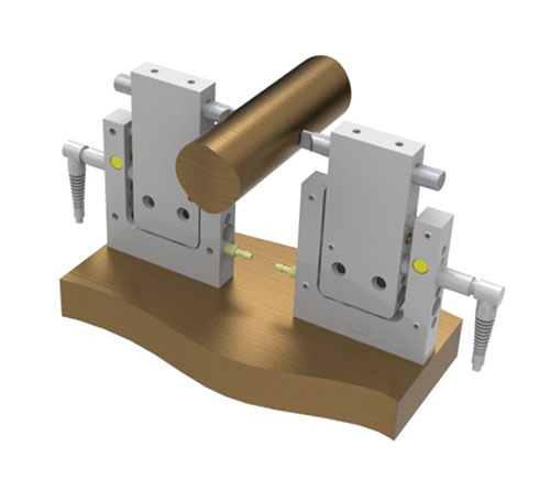
• Better. Another economical approach, shown in the third illustration, consists of a single LVDT in a fixture that measures the part “differentially” by mechanically linking the two parallelograms. With proper contact positioning and long lead-ins on the contacts, the part can slide easily into the gaging station. Versions with pneumatic retraction can further reduce potential abuse of the probe and parallelogram frame.
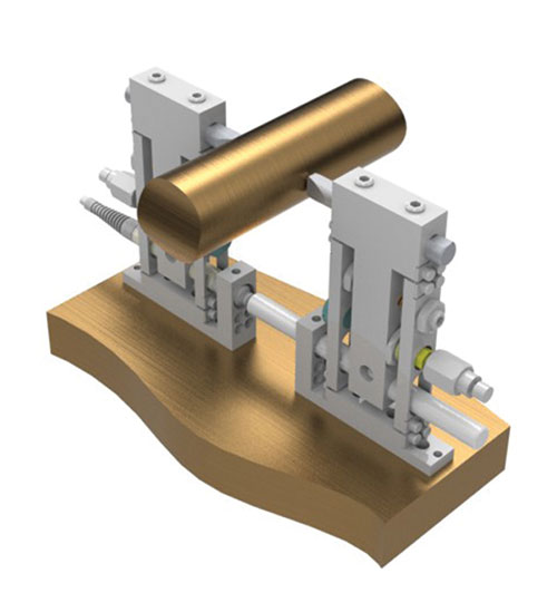
• Best. For highest accuracy and most lasting performance, configurations using a precision ball-bushing mechanism with pneumatic retraction like the one in the fourth illustration are recommended. These provisions protect the LVDTs from shock, as they only touch the part when the probes are released into position, and the ball-bushing construction provides extremely long life.
Concept Economies
Benefits of a flexible, modular system include:
• Reusability of standard elements. Once production of a particular workpiece has ceased, standard elements can be reused for another workpiece.
• A choice of different mechanisms for guiding the moving part of the stylus, selectable for the accuracy requirements of the measuring task.
• Reduced development and implementation time.
• Availability of the equipment: standard elements can be stocked by the supplier for immediate delivery when new gaging requirements emerge.
An initial gaging system can be constructed by the customer using standard elements obtained from a catalog. Alternatively, these elements can be ordered as a complete solution for the first setup, and then changed later as needed.
Modular, flexible gaging systems are still under active development. As noted above, these systems are not intended to replace either lower-precision handheld gages such as calipers and micrometers, or higher-precision tools such as snap gages, bench stands or more traditional ID/OD gages. Rather, these systems are intended to complement existing gages to help adapt inspection methodologies to an evolving manufacturing environment.
ABOUT THE AUTHOR
George Schuetz is director-precision gages for
Mahr Federal Inc. and a regular columnist in
Modern Machine Shop.