
More Parts, Less Space
High-density workholding techniques allow this shop to achieve high production-like efficiencies on an inexpensive CNC bed mill.

Share

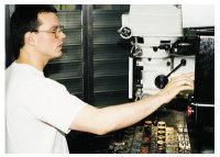
Tim Maple does most of the programming right on the shop floor.

High-density workholding minimized the impact of part loading and tool changes.
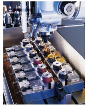
The pallet vise allows the shop to machine 12 parts in a single cycle on a 10 by 50-inch table.
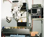
The multiple-part machining is executed on a very low cost machine tool.
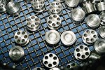
These are typical mold inserts. The tapered holes can be seen easily from the back, but you have to look close to see the small through-holes from the front.
Many shops that do high production machining are well acquainted with the notion of high-density workholding. Most frequently done with tombstone fixtures on horizontal machining centers, the idea is to gang as many parts as close together as possible and then machine them all in a single cycle. The process can drastically cut non-productive part load/unload and tool-change times as well as produce shorter net per-piece cycle times. Yet the longer overall cycle time (as multiple parts are machined), frees the operator to take on other useful off-line tasks, such as taking a more assertive role in quality management.
The technique is seldom applied on vertical machines, however, mainly because . . . well, come to think of it, there really isn't a good reason why. The machines are certainly capable and accessible—indeed they are far less expensive than their horizontal counterparts. And there are ample workholding methods, both standard and special, that lend themselves well to the process. So perhaps the only reason shops don't do more multi-part machining on verticals is simply because they are not accustomed to processing parts this way. It just doesn't cross their minds.


The thought did occur to Greg Pederson, who runs the mold making operation at Minnesota Rubber (Minneapolis, Minnesota). When this shop changed from machining multi-cavity molds out of a single block to making individual cavity inserts, it provided the opportunity to apply more efficient production techniques to the machining process. And the combination of a low-cost vertical machining platform with a high-density, multi-part workhold-ing system proved to be an extremely cost effective and efficient option. Here's how it works.
In-House Control
Minnesota Rubber and sister company QMR Plastics (River Falls, Wisconsin) are divisions of Quadion Corporation, a large manufacturer of custom molded elastomeric and thermoplastic components, with seven plants located in the United States, Europe, and Asia. All told, the corporation has some 750 molding presses and specialized engineering teams aimed at product and process development for the automotive, fluid delivery, and general industrial markets. Materials development is a particular strength of the company, both in elastomerics and in plastics. Their blue-chip customer list includes such well-known names as GM, Caterpillar, Honeywell, Volvo, Siemens, Bosch Brakes, Moen Faucet, Delta Faucet, Mercury Marine, and many others. For many of these customers, they take jobs from initial prototype development on through production.
They also develop most of the tooling in-house. The 50-person tool shop in Minneapolis makes most molds for Minnesota Rubber worldwide. But just because the company has substantial resources doesn't mean that this shop spends money cavalierly. They look closely at the shop's processes and its technical options, and apply appropriate technology to the job at hand. The mold insert machining operation is a good example of this principle in action.
The need for change was initiated in the molding process itself. Minnesota Rubber had traditionally processed parts in single-piece, multiple-cavity molds. But if there was a problem with any single cavity, the entire mold would have to be pulled for repair, removing all the other perfectly good cavities from service. To alleviate this problem, the company moved to cavity inserts. This way, if a single cavity goes bad, they can quickly pop the insert out of the mold, set another in place, and continue with the molding process.
Given that a lot of the molded parts are relatively small and round, many of the inserts are too. That provided the opportunity to manufacture many of the inserts out of round billets, 3 inches in diameter or less. And since the billets frequently are machined in quantities ranging from 200 to 300 pieces, the shop now had the opportunity to produce the cavities in a production-like process.
Tooling Up
The inserts typically are milled to form, and then undergo a succession of drilling operations in which the sprues—that is, the primary channels through which the liquid material flows into the cavity—are created. Initially, the drilling was performed as a secondary operation on a hand-fed drilling machine fit with a 5-seat collet indexer. The process was time consuming, laborious, and not all too accurate.
So Mr. Pederson sought out a new process to cost effectively eliminate the handwork, and to bring the machining and drilling together into a single handling per side. Safety and ergonomics were also factors. The idea was to increase both the productivity and quality of the process for as small a capital investment as possible. First they settled on purchasing a new three-axis CNC TRAK DPM bed-type milling machine, manufactured by Southwestern Industries (Rancho Dominguez, California). The next decision was how to get the most production out of the mill's 10 by 50-inch table, and that's where a high-density, multiple-part vise comes in.
According to Maurice Hagen, who worked out the process in detail, they knew they wanted to use as much of the machine table as possible, but the question was how. They began by looking at the maximum anticipated diameter of the billet inserts—3 inches—and then considered how to hold as many of those parts as possible, yet still remain flexible to accommodate the many other smaller stock diameters as well as the occasional square shapes that are machined.
Given the workpiece variability, some sort of vise workholding arrangement was clearly in order. The jaw stroke could easily accommodate the various sizes of stock. Moreover, using soft jaws would allow them to bore circular seats that would firmly grip and precisely center the mostly round workpieces. They considered using a succession of individual vises which, if all were mounted on a single baseplate, would be relatively quick to set up and still deliver multi-part machining. But this option still would prove relatively limiting in terms of the number of parts that could be machined with only a single setup.
Instead, they chose a standard high-density vise system designed specifically for this type of application, a "ClusterLock" pallet vise from Kurt Manufacturing (Minneapolis, Minnesota). The workholder clusters multiple clamping stations side by side, all on a single ductile iron base. Each clamping station holds two parts, with two movable jaws that close toward the stationary jaws in between. The version Minnesota Rubber uses has six clamping stations, and thus provides the opportunity to hold a dozen parts in a single setup. (Vises are also available with six, eight, or ten stations.) Every surface of the pallet vise is accurate to 0.0001 inch, says the manufacturer, and so it is more than accurate enough for the shop's requirements. Moreover, the clamping stations are so compact that the pallet vise allows them to set up the billets on a 3.125-inch center-to-center distance.
In Operation
According to Mr. Hagen, it took only three hours to bring the whole system on line. Subsequent setups have happened much quicker. While the pallet vise stays on the machine most of the time, there are occasions when other fixtures are used, so re-establishing location is an issue. First, they square up the vise on the table, and lock it down. Then they indicate off of a true setup hole that is bored in the left center of the first clamping location. This hole then is used as the program zero point for all machining routines.
Typically, they will rebore the vise jaws for each new setup. It's a step that isn't strictly necessary because the vises are sufficiently repeatable to reuse jaws previously bored for a given diameter part. And in some cases, they do just that. But there is such variety in the workpiece diameters that Mr. Hagen thinks it just as easy to go ahead and rebore the jaws in most cases. It's a standard boring routine, and the center line of each clamping station is already known. All the operator has to do is figure an offset appropriate to find the center point for the given diameter workpiece, enter the values, and the boring routine is ready to go.
A similar step-and-repeat methodology is used to generate part programs, which are typically prepared right on the shop floor. While the workpieces are not complicated, they do require a number of operations, and tools, particularly for the sprue holes. First the milling operations are completed, and then they begin drilling. The holes typically are stepped down four or five times, with only the smallest tool actually breaking through to the other side—and some drills are as small as 0.015 inch in diameter. According to operator Tim Maple, he begins with a spot drill and then might successively move down the hole with drills of 0.060, 0.040, 0.025, and 0.015 inch in diameter. Finally, the hole is finished with a "coning" operation, meaning it is reamed with a tapered tool which the shop makes itself that imparts a smooth 20- to 30-degree draft angle to the bore. Finally the part is flipped over and deburred.
Mr. Maple typically generates the program and runs it through completely on a single part. Once satisfied that the program is correct, he can easily repeat it at the other 11 workpiece positions by entering their location offsets into the control. To make the process more efficient, the CNC provides the ability to run each operation at all 12 workpiece locations before moving on to the next operation. For instance, all five holes in all 12 parts are spot drilled before moving on to the first size twist drill which, likewise, will be applied to all 60 holes in succession. This method keeps tool changes to the bare minimum, resulting in much shorter cycle times overall.
Faster And More Accurate
According to Mr. Hagen, the whole setup process takes about 45 minutes, and then they are in continuous production until the lot is complete. That's resulted in a major reduction in the time-consuming hole-making operations. "Before it took us about three minutes to make each hole when you include everything—setup and machine time," he says. "With the new process we've cut that in half."
There are accuracy benefits as well. Besides saving the time of an additional setup, combining milling and drilling on one machine has ensured that the part stays in one setup for both, meaning that location not need be re-established in mid-process. The accuracy of the drilled features relative to the milled features is as precise as the machine tool can execute. And in this case, Mr. Pederson says that the overall process accuracy has exceeded his expectations.
Add it all up and the shop has more than doubled its productivity and increased accuracy at the same time, while suffering no loss in flexibility. And they did all of this with a surprisingly small capital investment.
This is pretty smart stuff. Besides the setup advantages, Minnesota Rubber is taking most of the parasitic time associated with loading/unloading and changing tools for a single part, and "amortizing it across 12 parts." Or put another way, think of that wasted time as process overhead. With the multiple-part machining approach, they just have to pay the overhead on the first piece of a table load, and then in essence get the next 11 parts overhead-free.
That's a bargain you might expect out of a $200,000 horizontal machining center. But at Minnesota Rubber, they're getting it done on a $30,000 mill. That's a very good bargain indeed.


Read Next

3 Mistakes That Cause CNC Programs to Fail
Despite enhancements to manufacturing technology, there are still issues today that can cause programs to fail. These failures can cause lost time, scrapped parts, damaged machines and even injured operators.
Read More