Optimize Cutting Efficiency, Optimize Throughput
A machining process based on maximizing cutting efficiency, rather than speeds and feeds, offers aerospace component manufacturers an option to high speed machining when high material removal rates are required. The best strategy may be to apply both machining concepts.
High speed machining has been, and will continue to be, an eminent machining strategy in the production of aerospace components. The combination of very high spindle speeds, fast feed rates and small depths of cut delivers the surface finishes and accuracies required for parts such as frame components that often have delicate thin walls and bases. However, if there is one overriding “speed” the aerospace industry is most focused on in terms of component production, then it is the rate at which parts are completely machined and ready for assembly. Sandvik Coromant (Fair Lawn, New Jersey) believes that, for cases where substantial material must be removed quickly, shops may be better served to shift out of HSM gear and into a slightly slower, more efficient cutting process. The company refers to this process as high efficiency machining (HEM).
As the name implies, HEM focuses on optimizing cutting efficiency to maximize material removal rate. Unlike HSM, HEM typically throttles back spindle speed to a level that offers both high machine torque and power, and allows deeper depths of cut. Unlike traditional hogging, in which the cutting tool typically is fully engaged with the material, HEM cuts using a fraction of a tool's effective diameter to allow faster feed rates and higher material removal rates.
HEM likely won't supplant HSM in the production of aerospace components. The light, fast cuts inherent to HSM will still be required to for semi-finishing and finishing of certain critical part features. However, the potential benefits HEM offers in terms of roughing aluminum and titanium without damaging parts or prematurely wearing cutting tools make it worthy of consideration. This is especially relevant considering that, in the case of some aerospace parts, up to 95 percent of a billet workpiece may end up as chips.
Brian Davis, aerospace development manager at Sandvik Coromant, explains in this Q&A session how a blending of HEM and HSM techniques may be the best approach to quickest throughput of aerospace components.
- What are basic differences between HSM and HEM? HSM is a function of the machine in terms of potential spindle speeds and feed rates, and is also a function of the cutting tool in terms of geometries designed for very shallow depths of cut. The HEM strategy focuses more on the overall process and the component, in an attempt to minimize cycle times.
One aspect that HEM has in common with HSM is the lack of a universal set of process parameters that can be applied for every application. If you ask ten machinists for a definition of HSM, you'll likely get ten different responses. Sandvik Coromant considers HSM to involve spindle speeds in excess of 18,000 rpm. Typical HSM depths of cut may range from 0.010 inch for finishing operations up to 0.100 inch for roughing. In contrast, HEM may be a fraction of HSM spindle speeds, but multiple times HSM depths of cut. These parameters will vary greatly depending on workpiece type.
- What is the best type of machine for HEM? The most appropriate machine for HEM is a 50-taper horizontal machining center (HMC). An HMC for HEM needs only have top spindle speeds in the 12,000- to 15,000-rpm range, but should be high in both available power and torque.
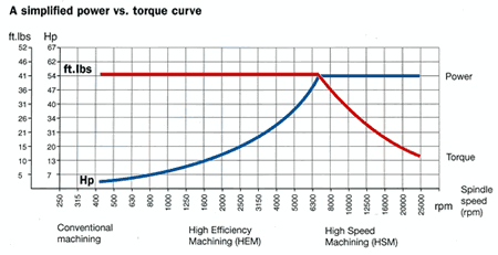
While feed rates and spindle speeds get primary focus in HSM, machine torque is as important as any other specification for HEM, as it is key to maximizing material removal rates. In settling on an initial spindle speed for an HEM process, it is helpful to understand the relationship between a machine's torque and power over the range of spindle speeds.
A machine tool will not deliver its maximum torque at maximum spindle speed, as torque begins to fall away at very high speeds. The goal is to determine the highest spindle speed at which torque and power are both sufficiently high for the cutting operation. This target speed varies per material and machine.
Aluminum, for example, is relatively soft and typically allows high cutting speeds. Considering the reduction in torque at very high spindle speeds, however, it is possible to stall a powerful machine tool while cutting aluminum. Machining titanium also requires high torque, but it is often done at much lower spindle speeds than aluminum.
Besides offering a rigid, stable platform to handle HEM's higher-than-HSM cutting loads, horizontal cutting allows the resulting large volume of chips to fall away from the part so as not to be re-cut, as can happen in vertical cutting. Obviously, very long aerospace components such as spars will require large vertical gantry machines. Through-spindle coolant is important not only to extend tool life, but also to assist in evacuating chips from the cutting zone. The machine's capacity to convey a large volume of chips must also be considered.
- What are the main tooling differences between HSM and HEM? Solid carbide tools are commonly used in HSM, and they often will have a polycrystalline diamond (PCD) coating. Indexable insert tools may also be used, but they are typically no larger than 2 inches in diameter. The cutting edge for tools designed for HSM's fast, light cuts are very sharp to allow good chip flow. These tools may not be appropriate for HEM, because they do not lend themselves to deep depths of cut. In some cases, a less-expensive, uncoated carbide tool may provide better material removal rates, as it offers sufficient depth of cut and higher edge strength to absorb greater chip loads. Indexable insert tools are more commonly used for HEM.
While HEM involves removing the largest volume of material as quickly as possible, it should not be confused with traditional hogging. In most hogging operations, the goal is to keep the cutting tool fully engaged in the material, in terms of length and width of cut. Hogging is also typically performed at much slower feed rates and spindle speeds.
Many modern indexable insert milling cutters have an optimal percentage of engagement—typically 30 to 40 percent of a cutting tool's diameter. By taking passes at only a fraction of the tool's diameter, much higher feed rates are possible, which increases material removal rate. This radial engagement not only provides the best entry angle, but also offers sufficient room for chip evacuation and ensures that coolant reaches the cutting edge.
Starting with a cutting tool's optimal percentage of engagement is appropriate if the process is known to be stable. If a particular setup is weak or a part design is sensitive to distortion because of cutting pressures, it is recommended to start out using half that percentage of engagement.
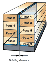
- Can HEM be used for thin walls? HSM is typically used for parts with very thin walls, as the small amount of tool engagement is less likely to cause a thin wall to deflect as the tool makes its cutting passes. Step support milling can make it possible to use HEM for some aluminum thin wall applications, despite the higher amount of tool engagement. In this technique, the cutting tool takes alternating passes down either side of the wall. The initial pass will only be a fraction of the depth of succeeding passes. This leaves material on the back side of the wall to help support the wall at the point of the cut.
Titanium is particularly apt to deflect in these situations, because its low modulus of elasticity causes it to spring back into its original position after a tool pass. For this reason, HSM should be used for thin wall features in titanium, as the cutting tool moves so rapidly across the surface that the material is less likely to move away from the cutting tool.
- Is HEM appropriate for forgings? HEM may be most useful in roughing large forgings. A titanium landing gear beam, for example, may start as a 2,000 pound forging but end up as a 600-pound part after machining. These forgings have drastic draft angles and ragged flash lines that would take an HSM process an exceptionally long time to remove. The best solution is to initially rough using HEM, and then use HSM for semi-finish and finish passes to limit distortion and provide a good surface finish.
Early Involvement
Mr. Davis notes that the aerospace industry differs from other industries in that there are neither new aircraft models each year nor significant component redesigns every year. Aerospace also leads the way in terms of safety regulations and the need for consistent, proven processes. It is for these reasons that many manufacturing methods are locked in at a relatively early stage of component design. The sooner that a cutting tool manufacturer can be involved in the design stage, the better the chance that the correct tool will be specified from the beginning of a component's life cycle, and the greater the long term payback and benefits.
Related Content
YCM Alliance Hits IMTS
YCM Technology has joined with other like-minded machine tool manufacturers to take a solutions-based approach to manufacturing.
Read MoreHow to Accelerate Robotic Deburring & Automated Material Removal
Pairing automation with air-driven motors that push cutting tool speeds up to 65,000 RPM with no duty cycle can dramatically improve throughput and improve finishing.
Read MoreRead Next
The Cut Scene: The Finer Details of Large-Format Machining
Small details and features can have an outsized impact on large parts, such as Barbco’s collapsible utility drill head.
Read More3 Mistakes That Cause CNC Programs to Fail
Despite enhancements to manufacturing technology, there are still issues today that can cause programs to fail. These failures can cause lost time, scrapped parts, damaged machines and even injured operators.
Read More.png;maxWidth=970;quality=90)
.jpg;width=70;height=70;mode=crop)





.png;maxWidth=300;quality=90)





.png;maxWidth=300;quality=90)


