
EDM Machine Probing Possibilities
Probing options for electrical discharge machining equipment range from simple to sophisticated. Here are options for wire, sinker and hole-drilling EDM.
.jpg;width=70;height=70;mode=crop;format=webp)
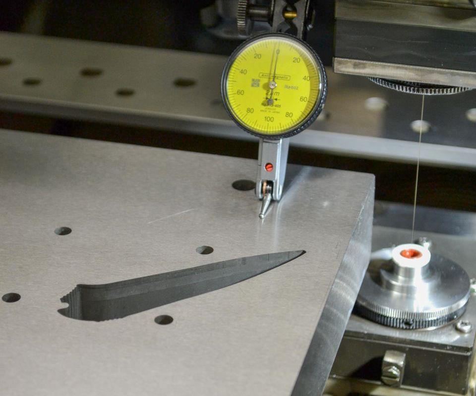
As an alternative to using a touch-trigger probe, a dial indicator can be used to perform 3D part leveling. This method is less accurate than touch-trigger probes and isn’t automatic, but it is less costly in that it uses a measurement device that most shops already have
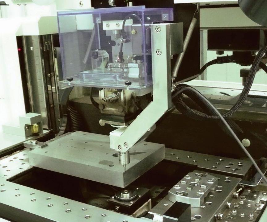
This touch-trigger probing system installed on a wire EDM unit can easily perform 3D part leveling to adjust the wire U and V axes perpendicular to the workpiece surface.
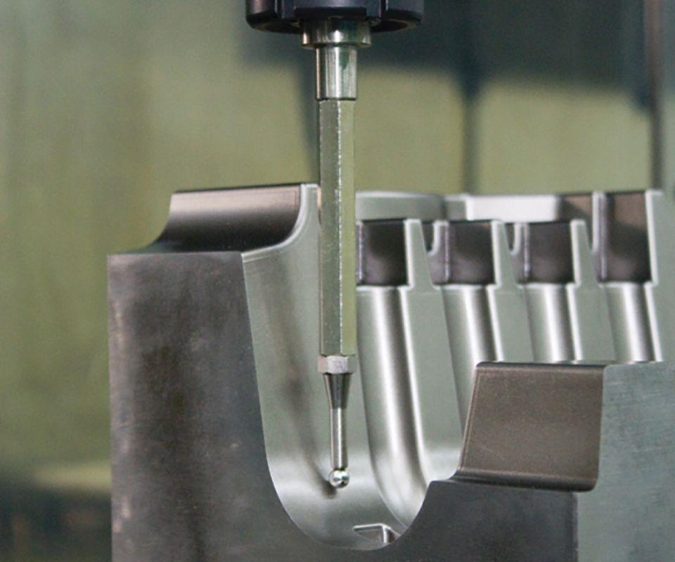
A rigid spindle ball is commonly used on sinker EDM units to determine part location and offsets.
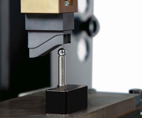
Similarly, a table ball can quickly determine electrode offsets.
Although probing routines are commonly used to speed setups, they can also be used to measure machined features for statistical process control and process validation.


On-machine probing with a spindle-mounted touch-trigger probe is commonly used on CNC milling machines to speed and simplify setups. After an automatic probing routine identifies the location of several points on a fixtured part or workholding device to establish the part’s exact location on a machine, the machine’s CNC can automatically adjust the native work coordinate system to match it. This eliminates shimming, part nudging and other time-consuming duties that would otherwise be required to get the part leveled and aligned to perfectly match the machine’s coordinate system.
The same goes for electrical discharge machining (EDM) equipment, be it for wire, sinker or hole-drilling EDM processes, in that probing cycles automatically establish workpiece and electrode alignment and size to reset the coordinate system and calculate 2D or 3D work offsets. That said, a touch-trigger probe isn’t always necessary for EDM equipment. In some cases, the electrode itself can be used as the probe.


Brian Pfluger, EDM product line manager for Makino’s Die/Mold Technologies division in Auburn Hills, Michigan, notes that while probing on EDM equipment isn’t new, there is a trend toward using probing not only to reduce setup times, but also to measure machined features for process control and validation. Here, he breaks down common probing options for the three EDM processes:
1. Wire EDM
The simplest form of probing on a wire machine is to use the wire energized at a low-voltage setting to electrically touch-off a part. This 2D probing routine can be used to identify the program starting point and determine part feature locations and sizes in some cases. However, probing accuracy using this method isn’t high, and probing routines are essentially limited to locating edges, corners and hole centers. (Most machine tool builders offer canned cycles for these types of probing routines. Mr. Pfluger notes that canned cycles like these on Makino’s Hyper I control with tablet-like interface include hyperlinks to supporting video and instructions for these and other cycles.)
The wire-probing pick-up cycles utilized by wire EDM require a clean and qualified surface on a workpiece that is free from debris and burrs. In addition, wire quality and wire cleanliness have an impact on probing pick-up accuracy. Poor-quality wire that might have oil or paraffin on its surface will reduce probing precision. Similarly, high-speed coated wire isn’t as accurate as traditional plain brass wire for probing, and it is the A-type coated wire that provides the best pick-up accuracy. Therefore, shops using high-speed coated wire might consider an alternate probing method.
For instance, Makino Inc. offers a manually loaded, touch-trigger probing system option for its wire EDM equipment consisting of a Renishaw MP250 probe and Erowa ITS air chuck. This system installs on the side of the machine’s upper head, but is designed so the centerline of the probe is located at the centerline of the wire. That way, probing can be performed within the entire available machine stroke. Probing accuracy using this method is ±1 micron.
The touch-trigger probe is also valuable in that it can be used to touch off the top or the sides of a part to establish a Z-axis plane. By probing three points on the top of a part, three points on one side and two points on another side, the zero point on a corner can be established, the machine’s U and V axes can be adjusted so the wire is normal to the workpiece surface, and the work coordinate system can be reset per the true location of the fixtured part. This is especially helpful for very large parts such as mold blocks that can be challenging to level and position accurately using shims and other methods in an effort to precisely align the part to match the machine’s native work coordinate system.
This probing method is also necessary when wire-machining polycrystalline diamond (PCD) inserts brazed onto cutting tool bodies. Using a machine’s wire as the probe isn’t possible given the small area on the insert land available to align the insert in the linear X and Y and rotational C axes. Touch-trigger probing of a few points on the insert is required to establish the location of the insert land in the locked C-axis position before wire-machining the proper rake angle.
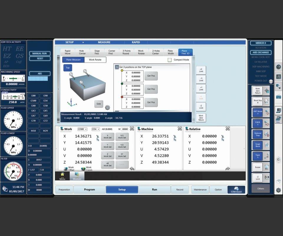
Although touch-trigger probing systems offer high accuracy and might be necessary in cases such as PCD insert machining, they are pricey machine options. As a result, Mr. Pfluger says Makino Inc. has developed an alternate, lower-cost, albeit more manual means of probing called 3D Plane Find that instead uses a common dial indicator that most shops will already have to perform 3D part leveling to adjust the U and V axes perpendicular to the workpiece surface.
Users install the dial indicator in the machine’s upper head and use it to find the location of three points on the workpiece surface just as the touch-trigger probe would. To do this, the setup person positions the indicator at one point, zeros the indicator and clicks a “get position” button on the machine’s control to record that point location. The dial indicator is then moved to a second point on the part surface, the setup person adjusts the head’s Z axis until the dial indicator goes back to zero, and that location is similarly recorded. After repeating this for the third point, the part surface plane is established after clicking a “compute angle” button on the control. The wire U and V axes can then be adjusted so that the wire is normal to the part surface. This process is slower and less precise than automatic touch-trigger probing, but it offers a less-expensive alternative using a common shop measurement device.
2. Sinker EDM
As with wire EDM, a sinker machine’s electrode can be used as the part probe. However, it similarly isn’t as accurate as more advanced probing options. For example, graphite electrodes could have debris on their surfaces and copper electrodes could have burrs from milling. Both situations can limit probing accuracy.
That’s why it is becoming more common to use a tooling ball system for probing. These systems use two rigid tooling balls, one mounted in the machine’s spindle (via a 3R, Erowa, Hirschmann or similar interface) and the other that installs on the machine’s table using a simple magnetic base. A low voltage applied to the spindle ball (approximately 5 volts) is used to electrically touch-off points on a part.
For each new job, a correlation between the position of the center of the spindle ball and the center of the table ball (therefore electrode and part) first must be established. The position of the table ball on the table isn’t important. In fact, it often must be moved depending on the size or geometry of the new part to be machined.
The spindle ball creates an offset to the part by touching off on the part to establish its actual location on the table. Makino’s Hyper I control offers seven canned cycles for this, the four most common of which are plate center, hole center, corner find and measure angle functions. The table ball is used to determine the true electrode size, location and offsets. Common canned cycles for this include plate centering, which is a four-sided pick-up function; hole centering; and three-point centering on the inner or outer diameter of a cylindrical electrode.
Users have the option of setting up all electrodes prior to machining a job to establish offsets for each, or the probing routines can be incorporated into the machining program cycle. With this latter method, the machine automatically performs a probing routine to determine the electrode center location as each new electrode is loaded into the machine during program operation.
In fact, Mr. Pfluger says Makino Inc. offers offline programming software for its sinker EDM equipment called EDcam that enables offline probing routine programming using 3D CAD data for the electrodes and workpiece as an alternative to traditional programing at the machine. The software also automatically calculates the discharge area based on the CAD models to determine the proper EDM power settings. The company is releasing a version of EDcam in April that offers an interface that’s similar to the Hyper I control. That way, the interface for machine setup and offline programming is the same.
3. Hole-drilling EDM
For aerospace and power-generation applications, such as drilling cooling film holes into contoured airfoil surfaces on turbine blades and vanes, touch-trigger probing is essential. This is largely due to the nature of the workpieces being drilled on five-axis EDM equipment.
Because these components are often castings, there can be variability from one part to another. A six-point probing routine is typically required for each blade or vane airfoil feature prior to drilling to adjust for true casting dimensions and establish the actual airfoil geometry and location on the machine.
For these applications, it is possible to use touch-trigger probing systems that feature optical or radio communication between the probe and data receiver inside the machine, such as the Renishaw optical OMP 400 or radio RMP 600. Mr. Pfluger says there really isn’t a difference in cost or accuracy between the two. However, there can be interference/miscommunication issues when using an optical system if a shop has multiple compact machines (such as hole-drilling EDM units) that are installed closely together. For situations such as this, radio communication is more secure because specific frequencies can be used on specific machines.
Although probing is essential for these applications, some shops choose not to perform on-machine probing given that it reduces the time a machine is actually machining. Instead, they might perform off-line probing on a coordinate measuring machine (CMM) and transfer the measured offsets to the offset registers in a machine’s CNC. This requires standardizing on a pallet workholding method for repeatable part positioning on both the machine and CMM.
EDM Machine Probing for Process Control
Mr. Pfluger says that, while many EDM users understand the value of probing to speed setups, some don’t fully tap the potential that probing offers in terms of measuring the size of a machined feature or determining its location, which is valuable for statistical process control (SPC) analysis and machining validation. These probing routines can be included as part of the part program to enable feature measurement to happen automatically after the EDM process is completed. Measurement data, such as the diameter of a hole or its center location, can be exported and saved.
Although it’s not possible to use the same machine that produced the part to measure it, it is possible to validate the process via probing before the part is removed from the machine. This is done by establishing a correlation between the on-machine probing measurements to a master CMM inspection device on a qualified part. If on-machine probing measurement data shows there is a discrepancy, then adjustments can be made and additional machining can be performed to bring the part closer to the nominal target values. With correlation, if on-machine probing measurements are within specification, the user is confident that the part can be removed from the machine with no need for rework.


Related Content

How to Tackle Tough Angled Pocket Milling With Two Tools
Milling a deep pocket with a tight corner radius comes with unique challenges, but using both a flat bottom drill and a necked-down finishing tool can help.
Read More
Buying a Lathe: The Basics
Lathes represent some of the oldest machining technology, but it’s still helpful to remember the basics when considering the purchase of a new turning machine.
Read More
All-Around Mill Improves Productivity and Cost for Valve Job
Adopting a mill with a double-negative rake and pockets compatible with multiple insert geometries enabled Progressive Metal Service to increase feed and lower scrap rates for a valve.
Read More
A New Milling 101: Milling Forces and Formulas
The forces involved in the milling process can be quantified, thus allowing mathematical tools to predict and control these forces. Formulas for calculating these forces accurately make it possible to optimize the quality of milling operations.
Read MoreRead Next

3 Mistakes That Cause CNC Programs to Fail
Despite enhancements to manufacturing technology, there are still issues today that can cause programs to fail. These failures can cause lost time, scrapped parts, damaged machines and even injured operators.
Read More

The Cut Scene: The Finer Details of Large-Format Machining
Small details and features can have an outsized impact on large parts, such as Barbco’s collapsible utility drill head.
Read More