
Practical Tips For High Speed Machining Of Dies And Molds
In die/mold work, the programmer can make the HSM process dramatically more effective. Here are some tips.


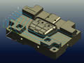
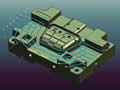
Fig. 1—Machining with a convention pattern (left) causes the tool to spend some of its time slotting. A follow-part pattern (middle) makes the process more efficient by avoiding slotting. A trochoidal pattern (right) can make the process still more efficient by limiting tool embedding.
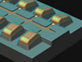
Fig. 3—The tool paths to the left send the tool up steep slopes. Changing the toolpath angle to 45 degrees (right) helps to reduce the load on the tool.
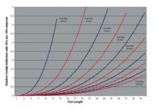
Fig. 2—Increasing tool length by 20 percent increases deflection by 50 percent.
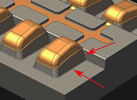
Fig. 4—Increasing this shut-off fillet radius reduced machining time for this part by 20 percent.
Increasing spindle speed, reducing chip load and rounding the sharp corners in the tool paths are some of the important considerations for successful high speed machining. However, NC programmers and machinists who stop at these considerations find themselves either breaking tools or scaling back on parameters such as stepover, feed rate and depth of cut. This is serious, because if high speed machining does not reliably deliver significantly faster throughput, then the high speed machines are not worth the investment.
More successful machinists and programmers realize that high speed machining is a fundamentally different way to machine. They look for ways to continuously improve their processes on high speed equipment. Some of the improvements can be quite simple. That is the case with the tips presented here. What follows are ideas that you might adopt today to better realize the value of your own high speed machining process.


1. Aim For Constant Material Removal
In an optimized system, all elements operate just below their peak capacities and none of them are overloaded. This is what we should strive to achieve in high speed machining. To avoid tool damage, speed and feed should remain in bounds for the peak loading encountered in the tool path. However, setting speed and feed in this way leaves the tool cutting slower than it should during all of the non-peak-loading periods. We want the tool instead to operate at the edge of its threshold throughout the cut. That is, we want constant material removal or consistent chip load. If there is inconsistent chip load, then one of two things is happening: Either the process is damaging tools, or else it is running too slowly.
Optimizing the rate of metal removal in roughing is the most important step in CAM programming. The depth of cut and stepover recommended by machining tables for a given combination of tool and material assume that you are roughing at the same stepover throughout the tool path. If your path involves a slotting move or careless corner embedding, however, then the tool could encounter a lot more material than anticipated.
Simple offset patterns work well only if all sides of the material to be removed are open. If you have walls adjacent to the area you are trying to rough, then this pattern could cause the tool to slot through material. (See Figure 1.) A better option is to use a follow-part offset pattern. Such a pattern avoids slotting by starting away from the part walls and working in. Even though this tool path includes many rapid moves, the overall machining time is reduced because of the increased stepover this pattern allows. An even better option is to use a trochoidal pattern that monitors the amount of tool embedding to maintain a consistent threshold.
2. Stick To Z Levels
In most cases, finishing 3D surfaces through Z-level operations (also known as “water line” or “constant Z” machining) provide much better material engagement and more consistent finish than projected finishing operations. Z-level operations guarantee that the material removal rate and tool engagement are consistent, with fixed axial depths of cut and top-down cutting. In contrast, projected raster operations climb up and down depending on the part geometry, suffering significant spikes in axial engagement when they climb steep slopes. Again, if these areas of peak loading do not damage the tool, then the non-steep parts of the process are cutting too slowly.
3. Know Your Controller
Some controllers feature high speed processing modes that provide for aggressive acceleration and deceleration rates during roughing operations where submicron accuracy is overkill. For example, on Makino machines using Fanuc controllers, simply turning on the M251 code before roughing cycles could reduce roughing time by 30 percent. Siemens’ Sinumerik 840D controller offers a similar high speed cycle (Cycle 832), which allows users to set various velocity optimization modes. Advanced CAM systems such as NX from UGS provide customizable operation templates where these settings can be set up once and then used automatically.
4. Shorter Tool Length is Better
A cutting tool is a cantilever beam, with the cutting force acting at its free end. Proven physical equations show that the deflection is exponentially proportional to the length of the cutting tool. For example, a 6-mm diameter tool set at 24-mm length could deflect 50 percent more than the same tool set at 20-mm length. (See Figure 2.)
The deflection at the cutting edge is the primary cause behind various negative effects such as chatter, wobble and impact loading. Hence it is important to keep this deflection to a minimum. Reducing the tool length is the easiest way to control tool deflection and still maintain high material removal rates. The tool length advisor in NX Machining from UGS prompts the user with the shortest length of the tool that would be sufficient to machine a given geometry.
5. Never Climb Straight Up
Any hiker can tell you that climbing a hill on an angle reduces the effective slope and makes the going easier. Steep hills are hard on end mills as well, because they engage more material on the uphill side. As the slope gets steep (on the draft faces of most die cavities and cores, for example), the axial engagement can spike dramatically. This could break the tool.
There are two techniques to mitigate the engagement spikes that result from steep climbs. One is to change the zigzag angle so that the tool approaches these steep walls at a 45-degree angle rather than plowing head-on into them. Climbing up at an angle reduces the effective slope and relieves the overloading. (See Figure 3.) A side benefit of cutting at 45 degrees is that the fillets running at 0 and 90 degrees are only momentarily engaged during each pass, giving the tool time to recover. Cutting parallel to these fillets would otherwise increase the load during a few passes, possibly elevating cutting tip temperature and weakening the tool.
Another technique to avoid overloading the tool while cutting steep walls is to pre-machine these walls using Z-level operations. Zigzag area milling the entire part can come next, but the pre-machining of these walls means that the zigzag milling can avoid loading the tool when these walls are encountered.
6. Interact With Your Tooling Designer
Certain features require more careful programming and machining than others. Potential examples include the small concave fillet radii and narrow slots that are often encountered in mold components. Educating your tooling designer about the machining challenges of these features could make your life a lot easier. For example, most shut-off mold surfaces do not need tight vertical fillets and slots. These could easily be modified to make machining of these parts easier and quicker. (See Figure 4.) In short, effective high speed machining may involve not just spindle speed, feed rate and toolpath smoothing, but also attention to the nature of the tool paths themselves, and it may even involve greater communication as well.
About the author: Edwin Gasparraj is a product manager with UGS based at the company’s Milford, Ohio, office.


Related Content

CAD/CAM System Requirements: An Overview
CAD/CAM programs are among the most demanding kinds of computer software. Smooth operation requires careful consideration of computer specifications.
Read More
Large-Format Machining With Small Cutting Tools and Dynamic Motion
Napoleon Machine, a defense contractor that provides parts for the M1 Abrams tank, recently took advantage of a CAM feature that allowed the company to streamline its cutting strategies and program offline. Here’s how the shop cut cycle times nearly in half with its large-format five-axis machining operations.
Read More
How Integrated CAD/CAM Transforms Inventions Into Products
The close connection between CAD and CAM is what links creative ideas to practical production for this unique custom manufacturer.
Read More
Automated CAM Programming – Is Your Software Really Delivering?
A look at the latest automation tools in Autodesk Fusion 360 software and how forward-thinking machine shops and manufacturing departments are using them to slash delivery times and win more business.
Read MoreRead Next

Constant Material Removal: The Key To Hard Milling
Features of the CAM software can keep the cut from exceeding the tool’s limits, without compromising part quality or productivity.
Read More
The Cut Scene: The Finer Details of Large-Format Machining
Small details and features can have an outsized impact on large parts, such as Barbco’s collapsible utility drill head.
Read More
3 Mistakes That Cause CNC Programs to Fail
Despite enhancements to manufacturing technology, there are still issues today that can cause programs to fail. These failures can cause lost time, scrapped parts, damaged machines and even injured operators.
Read More