
Race To The Rocket
Integrated CAD/CAM software helped this custom-car shop bring five-axis machining in-house to create a one-off concept racer.


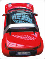
Here's how it all came out at the end.
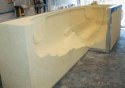
The main body mold was machined in four sections and then assembled. This view shows three of the sections in place.
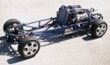
The chassis was fabricated from tubular steel.
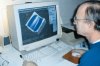
This shaded model is of the mold used to fabricate the engine hood panel.
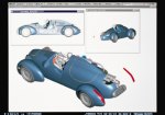
Transparent and cutaway views of the solid model allowed Mr. Balaschak to visualize the overall appearance and to ascertain if proper clearances were met.
George Balaschak knew that in designing and building the E-Go Rocket he was crossing uncharted land. The project would entail more than just creating another concept car for a Swiss customer to display at the annual Geneva Auto Show. Mr. Balaschak, president of TLC Carrossiers Inc. (West Palm Beach, Florida), realized that he would be entering a race to integrate design and manufacturing in his five-person custom-car shop. Intent on better controlling cost and squeezing out leadtime, he had decided to bring his five-axis machining work in-house. "My vision was to model the car electronically and then machine the molds for the composite body panels in our machine shop from that model," he explains.
Adopting the philosophy of integrated manufacturing for producing this year's car, the third such creation commissioned by Frank Rinderknecht of Rinspeed Design, was a tall order. In just six months, Mr. Balaschak would have to solidify a hazy idea based on the old Bonneville salt flat racers, buy the necessary manufacturing software and CNC machinery, and build the car.


When the manufacturing machinery was in place, however, he and his staff would be able to capitalize on the parametric CAD/CAM software that would help automate the total design-through-production process. TLC had used the product-modeling software from Parametric Technology Corp. (Waltham, Massachusetts) to design the previous year's concept car, the Mono Ego. This year Mr. Balaschak would extend his proficiency with the "Pro/ENGINEER" software by using the integrated manufacturing simulation software.
"The Rocket is a clean-sheet design inspired by the belly tank cars that raced at Bonneville," Mr. Balaschak says. "These old racers are called belly tank cars because they were essentially four wheels and an engine mounted on the aerodynamic, dropped belly tanks from Air Force fighter planes of the fifties. Like these racers, our car is small and light but is a street-legal single-seater that is fun to drive."
Once Mr. Balaschak and his team had created the electronic product model of the E-Go Rocket in CAD, they fabricated a tubular chassis out of 4130-chromium molybdenum steel. The chassis was designed with the appropriate mounting points for the steering rack, independent suspension, a supercharged Ford Cobra engine (mated to an Audi transmission and differential assembly), and other purchased and fabricated components. The chassis provided mounting points for the body and interior assembly.
Computer-Aided Puzzling
Although assembling the power train from standard components meant not having to design complex systems, the components posed a packaging challenge. "The car was small for such a large power train," explains Mr. Balaschak. "If we made the body too narrow, for example, the valve covers would stick out. Fitting the street-legal exhaust system with its four catalytic converters, two mufflers, and two large exhaust pipes in a mid-rear engine configuration was difficult, too. The chassis or the control arm would often be located where we wanted to put exhaust components." Another rather important piece of the packaging puzzle was the driver. Mr. Balaschak used an electronic mannequin from the software's human factors library and positioned this six-foot-tall "Oscar" in various driving postures in the vehicle to find the proper compromise of ergonomics and aesthetics.
No IGES files for the power-train components were on hand for this computer manipulation. So Mr. Balaschak and his design team had to develop electronic models of the various standard components and subassemblies before they could begin juggling the pieces. They generated this solid model part geometry from the few blueprints that were available and by digitizing three-dimensional point data gathered from actual parts with a FaroArm measurement system (Faro Technologies, Lake Mary, Florida). Then they put the 3D CAD parts and subassemblies together, specifying the relationships among components.
As Mr. Balaschak and crew wrestled with the packaging puzzle by modifying body, fenders and chassis designs, the CAD software tracked and maintained all the relationships. Because the software stores each part in the electronic model as a collection of features defined as dimensional and nongeometric parameters, the value of each parameter changes as designers modify the model. As a consequence, the unified electronic model updates automatically. The software lets TLC do all the prototyping electronically and eschew the traditional method of carving a clay model, digitizing it and later engineering the drive train and other systems to fit. By defining the relationships among all the components, Mr. Balaschak could keep juggling aesthetic and functional changes in, say, a fender and have the mating pieces update automatically.
"Traditional methods of packaging the car would have taken much longer," notes Mr. Balaschak. "For the exhaust system alone, the software cut the design, packaging and fabrication time by a third. Once we knew that the catalytic converters, mufflers and pipes would fit, the guys in the shop made a simple wooden fixture from a 2D section drawing in order to position and hold some of the exhaust components for tack welding. We didn't require expensive production fixtures; we just needed something to help us position the exhaust pipes where they were to protrude through the body."
In the process, the technicians ran into a surprise: The muffler was a little larger than the manufacturer's blueprint said it was. "Our design called for a very tight fit, so we had to do a little ad-libbing on the car itself," Mr. Balaschak says. He was able to reflect the difference afterward in the electronic model and preserve and record the actual relationships between the exhaust system and body.
Manufacturing Ups The Challenge
Given the time frame, making all the components fit seemed enough of a test. But puzzle completion wasn't the biggest challenge that TLC encountered on this project. "The most exciting part was cutting the body-panel molds on our new five-axis bridge mill," says Mr. Balaschak. He bought a used machine, measuring 144 inches in X by 60 inches in Y by 32 inches in Z, and retrofitted it with new servomotors and a PC-based touch-screen CNC from MDSI (Ann Arbor, Michigan). Not only did he have to make time in his already tight schedule for the machine purchase and makeover, but he also faced the big leap to CNC from the conventional manual lathe, mills, saws and small hand tools his shop had used exclusively in the past.
On top of integrating the retrofitted CNC machine into his operation, Mr. Balaschak also had to learn "Pro/NC," the NC programming applications in the CAD/CAM system. He would use the mechanical and NC programming software to design models of the body molds and generate the tool paths to cut them—all without any formal training.
Because of the associative nature of the product modeler, he was able to create the molds for the body panels electronically from the surfaces stored in the database. The software updated the molds and tool paths automatically whenever the design of a part changed. "To create a solid model of each mold, we first generated a two-by-four-by-eight-foot solid block to represent the foam to be cut and intersected it with the relevant panel surfaces. Then we just told the CAM software to machine it."
A Powerful Programming Tool
Mr. Balaschak now could concentrate on programming the five-axis moves, some of which included specifying tool orientation. For example, a particular tool angle was necessary for undercutting a small shelf on a part. Here he created a reference plane and coordinate system from which to position the tool. "We were actually machining in three axes at that point, if you don't count the fourth and fifth axes for positioning," he says.
Another programming help was the ability to create mirror images not only of the geometry but also of the tool path. "Because the vehicle is symmetrical, you can save a lot of time by just designing one side of the car and using the mirror-image function to create the other side," notes Edwyn Pyron, a PTC manufacturing consultant. "Mirror imaging the tool path saves even more time because you bypass the work of programming another part."
Programming the first mold, the one for the left-hand fender, took about 3½ hours. Mr. Balaschak and Mr. Pyron then spent another 45 minutes verifying the program with a simulation module in the software. The exercise saves time, reduces potential scrap and offers visual verification by displaying the reference model and workpiece with the selected tool moving through the cutter path.
After that, with the software's mirror-image feature, programming the right-hand fender took only 15 minutes. "And we didn't check it," recalls Mr. Pyron. "We were able to go directly to the foam and cut it."
By the time it came to machine the hood mold, Mr. Balaschak had gained confidence in his ability to generate error-free programs. He decided that verifying them was not worth the extra time. "We were in a big time squeeze, and the clock was ticking fast," he explains. "So the time savings of machining unchecked programs far outweighed the small risk of ruining a block of foam." The gamble paid off. In the end, he did not ruin any of the molds, even though he was a novice with the programming software.
Although the typical cutting job required three passes, the actual number of passes depended on the part. "On some small parts, for example, we went right to the finishing cut," says Mr. Balaschak. "There was no sense in taking roughing cuts on them. On other parts, though, we took as many as five passes because of depth constraints when reaching into the body mold."
When digging deep into most body molds with a 1-inch ball mill, Mr. Balaschak's crew roughed with a 3-inch stepover at the full 6-inch tool depth. This technique formed blocks or cells in the foam, which the technicians could break or saw out manually, rather than spending the time turning the material into dust. Then the machine would clean up the surface at a 0.950-inch stepover, leaving 0.250 inch of stock. "On the finished surface, we used a tenth stepover and set the scallop height control for 0.005 inch, which leaves a nice surface," Mr. Balaschak says. "We could have tightened the scallop control, but that would have traded off machining time."
A Race Won Big
In the end, the seamless integration of design and manufacturing allowed TLC to machine the molds, lay up the body panels and finish assembling, painting and test-driving the car in a month. "We machined the first mold on January 24 and delivered the car on February 24," says Mr. Balaschak. "The last mold we cut was the license-plate frame on February 18, a Wednesday. We worked all night making the composite part, installed it on Thursday, painted the body Saturday and put the whole body on the chassis early Sunday morning." Sunday and Monday were spent taking publicity photographs and videos. Tuesday the car was air-freighted to Switzerland.
"Meeting our delivery date meant programming tool paths, machining molds and laminating composite panels simultaneously," he continues. "Without the computer modeling and simulation programs, the project would have taken much longer and cost twice as much. Using the computer was a rather bold approach, but it let us create a one-off car economically." Combining good craftsmanship with computer power controlled costs and won the race against time.
About the author: Miles Parker writes here on behalf of Parametric Technology Corporation, but is also manager of the Committee for the Advancement of Competitive Manufacturing at the University of Rhode Island.


Related Content

Digital Twins Give CNC Machining a Head Start
Model-based manufacturing and the digital thread enable Sikorsky to reduce lead times by machining helicopter components before designs are finalized.
Read More
Building a 5-Axis Cell
5-axis machining has taken over the metalworking industry, but what goes into a high-functioning 5-axis machining cell?
Read More
Inverting Turning and Five-Axis Milling at Famar
Automation is only the tip of the iceberg for Famar, which also provides multitasking options for its vertical lathes and horizontal five-axis machine tools.
Read More
Which Approach to Automation Fits Your CNC Machine Tool?
Choosing the right automation to pair with a CNC machine tool cell means weighing various factors, as this fabrication business has learned well.
Read MoreRead Next

The Cut Scene: The Finer Details of Large-Format Machining
Small details and features can have an outsized impact on large parts, such as Barbco’s collapsible utility drill head.
Read More

3 Mistakes That Cause CNC Programs to Fail
Despite enhancements to manufacturing technology, there are still issues today that can cause programs to fail. These failures can cause lost time, scrapped parts, damaged machines and even injured operators.
Read More