
Rapid Milling For Prototypes
Rapid milling is different from CNC milling in that it relies on high-speed capability and techniques to the extreme. For prototyping, rapid milling becomes a powerful tool that provides faster feed rates, better finishes with less handwork, higher accuracies, and a very wide choice of materials.


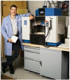
Designcraft's founder and president Greg Borucki (at right) is resting more than his elbow on a machine designed for rapid milling. The shop's ability to choose the best approach to prototyping also rests on this and other techniques, each ideal for certain situations. The mill shown here is the shop's newest machine tool, a model VTX-1 from Defiance machine & Tool.

Sudden changes in a milling cutter's direction are likely to create the risk of gouging unless the look-ahead features of the CNC detect the change in time to initiate a strategic correction in feed rate.
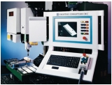
The capabilities of a CNC system largely determine the ability of a milling machine to produce accurate shapes at high speed. CNCs such as Creative Technology's Evolution feature high speed data processing and dynamic "look-ahead" for rapid milling applications. Designcraft has two VMCs retrofitted with Evolution CNCs.
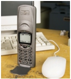
Prototypes for this satellite phone are typical of the items Designcraft produces for its customers and one of the very few that can be shown. Because design is so critical to the commercial success of a product, prototypes like this are rarely available for viewing by the outside world.
Designcraft Corporation of Elk Grove Village, Illinois, is an outstanding model and prototype shop. Many innovative products like the Motorola "flip phone" have taken their first physical shape here. The tools to transform a concept into a physical prototype have changed a lot over this company's 18-year history. The most recent and dramatic changes, though, have been the implementation and optimization of rapid milling.
Designcraft Corporation has evolved from the roots of hand model making, through stereolithography to rapid milling. Greg Borucki, president and founder, states that through using the old manual machines and extensive handwork in 1988, the first flip phone took a full month to become a realistic looking and feeling prototype as created from 2D CAD drawings. By 1992, using 3D CAD/CAM and stereolithography, they were able to create a prototype in less than seven days. Now, Designcraft uses rapid milling to create new conceptual models at a blistering rate of one new model per week!


What's so great about a full week for models now, if they took less time before with stereolithography? That's where this story really begins, with the benefits and possibilities rapid milling provides.
What Prototypes Are Good For
The purpose of prototyping is to get a physical model, enabling the "touch and feel" phase of product development. Mr. Borucki claims that rapid milled prototypes made of engineering thermoplastics have a more "honest" feel. The virtually unlimited choice of materials can deliver prototypes with the precise structural characteristics and the feel that should be expected from production parts.
Mr. Borucki adds, "Rapid milling reduces handwork, providing several benefits. It's hard finding good help today for the monotonous work of filing, sanding and polishing parts. Further, no matter how good they are, each finishing stroke on a part reduces its accuracy from the CAD information the part was designed to be. With stereolithography parts, no one wants to work with the irritating chemicals and fumes. By reducing the handwork, rapid milled models are simply better in spite of the extra time required. They're worth the difference in time and cost."
Does all this mean that Designcraft Corporation's two stereolithography machines are sitting idle? Not at all. "Our stereolithography machines are busier than ever," reports Mr. Borucki. "There are many cases where stereolithography parts meet the need just fine, and the lower cost can be an advantage hard to overcome with any accuracy or materials. This serves only to emphasize how rapid milling, as with all our current prototyping methods, is just one more tool in the box, another way to approach the job."
What about the old-fashioned way, building models by hand? Although the tools of the trade cost much less, lowering overhead, this method could not compete today. All the tedious work makes manual models late for delivery and much more costly, generally by three or four times. Still, the manual tools and artisans are crucial to the process yet today. "All rapid prototyping techniques need hand finishing in varying degrees to give the finishing touches. Our staff's artistry helps separate us from competition with a better end product," says Mr. Borucki.
Table I (below) gives a list of the three prototyping methods used at Designcraft Corporation and summarizes some of the advantages and disadvantages cited by Greg Borucki for most cases.
Table 1 - Comparison of advantages and disadvantages for rapid prototyping methods
Advantages Disadvantages
Hand Models Lower overhead in tools
Higher cost by 3 to 4 times
Less accurate
All handwork
Much longer delivery
Stereolithography Lowest cost
Fastest delivery
Very expensive equipment
Limited choice of materials
More hand finishing
Irritating, expensive chemicals
2D layering buildup of part
Poor presentation "feel"
Rapid Milling Unlimited choice of materials
True part "feel"
Highest accuracy
Less finishing time; can machine to finish in some cases
Better customer impression and easier "sell" of the part
True 3D surfacing of part
Moderate equipment cost
Costs about 10% more than stereolithography
Delivery 10 to 15% longer than stereolithography
More build time for fixturing
Hollow parts need extra time for milling the inside
Two Key Technologies
Looking more deeply at rapid milling for prototyping, there are two key technologies that enable it to contribute effectively to the bottom line at Designcraft Corporation. First, extreme high-speed CNC with look-ahead is essential. Ordinary CNC milling may be an asset in some areas of endeavor, but it is just too slow for effective prototyping. Second, fast and effective cutter path generation was the final bottleneck that made rapid milling a real rapid prototyping or time compression technique.
High Speed CNC
So how fast do we want to go for rapid milling? Obviously, that can vary depending upon the material and cutters. If a machine won't mill accurate contours at 200-ipm feed rates or higher, it's not likely to be useful for prototyping. Faster feed rates to 600 ipm or more are better.
A machine's ability to rapid-traverse at a given rate does not imply that it also can cut accurately at that speed. The control may limit feed rate operations to a significantly lower rate, and even then, the results may be useless, with distorted geometry suffering from gouging and overshooting. Again, not just any CNC mill will be a useful tool for prototyping. It must be capable of accuracy at the feed rates you need.
When we watch a CNC generate a 3D shape, we should see the cutter flowing smoothly over the surface. A lot of information is actually flowing in a rapid stream to create this illusion. First, we have to get the cutter path into the CNC. Then the CNC must load it into a buffer for execution. Each block is interpreted, breaking it into pieces important for different axes or sub-parts of the machine. Each individual programmed motion is broken into even smaller segments for interpolation. Then, a master timing controller synchronizes all the activities into one grand scheme by coordinating all the little sequences.
From CAD/CAM To CNC
The first stage of the data flow is generally into the machine from the CAD/CAM system. Historically, this has been achieved by DNC (direct numerical control). DNC "spoon feeds" the data into the CNC several blocks at a time, eliminating the need for the CNC to store the entire program in its own memory. "Distributed numerical control" is a simpler implementation of DNC that simply serves as a storage and retrieval system for shorter CNC programs. DNC normally communicates with the CNC control at 9600 baud, resulting in a maximum of 960 characters per second (cps), about 48 program blocks. High speed milling requires much faster throughput, often claiming 1,000 block-per-second or higher data rates. Today's prototyping, rife with long cutter paths, needs the ability to get the data through the CNC faster than DNC. Direct networking of the CNC to its data source is required. Networking delivers the data to the CNC over a thousand times faster, with capacity to spare.
Examining a typical program data block helps reveal why we need such fast data throughput:
G1 X123.456 Z234.567 <Enter> <Linefeed>
Program blocks for 3D contours typically include two or more axes of position command. Additional feed rate, axis commands, or other codes add to the data requirement. Even transparent characters like the spaces and linefeed take transmission time. Experience indicates that 3D contour programs are made up of thousands or even millions of lines or blocks, each about 20 characters in length.
If DNC communicates with the CNC at 960 cps, then we can see that only 48 typical program blocks could be transmitted in a second, even under the best of circumstances. This simply isn't enough to provide the results demanded for high speed milling.
Most computer networking today uses Ethernet at either 10 or 100 megabits per second. That means that 1 million or 10 million characters can be transmitted in a second, again under the best of circumstances. This is more than a thousand times the communications rate of most DNC systems. At the lower network standard, 1 million cps, we can still transmit more than 50,000 typical-length blocks of CNC program data per second. This provides very adequate bandwidth for data flow to the CNC.
Data Inside The CNC
Once the data gets to the CNC, though, how does the CNC handle the data? There are three crucial time specifications used in a CNC, the block transfer time, interpolation time, and the servo cycle time. Each is distinctly different, and each has the potential of limiting your CNC from meeting your needs.
The block transfer time is the time that the CNC takes to absorb a single block of program information. If the block transfer time is 3 milliseconds (ms), then the CNC is capable of absorbing 333 blocks per second (bps). The ability to absorb program information quickly is very important to making the CNC run smoothly.
The interpolation time is the time the CNC works with to create interpolation segments. Although you may see a single straight-line or circular move as you watch your machine, the CNC control is breaking those moves into the smallest segments it can based on this timer, in order to coordinate the machine movements as accurately as possible. Although arcs and circles are often entered as single-line commands, the CNC control breaks them into small, linear movements to create the illusion of a circle using axes that are perpendicular but can't actually rotate at all. The interpolation time is the limiting factor for how small the increments can be at any given feed rate for any given interpolation.
The servo cycle time is the time that the controller takes to command the axes and verify the axis positions. This is the lowest level motion timer in the bowels of a CNC control, the bottom line in performance!
Look at the sample listing of CNC timer speeds in Table II below. It shows the distance the axes move in a given time slice at three sample feed rates, 100, 400 and 1200 ipm.
Table II - Distances traveled for various CNC time cycles
Time/
Milliseconds
Cycles/
Second 100 ipm Distance Traveled
400 ipm 1200 ipm
20 50 0.0333" 0.1333" 0.4000"
10 100 0.0166" 0.0667" 0.2000"
3 333 0.0050" 0.0200" 0.0601"
1 1000 0.0016" 0.0066" 0.0200"
0.4 2500 0.0007" 0.0026" 0.0080"
0.1 10000 0.0002" 0.0007" 0.0020"
As you can see in the table, if a CNC machine, controlled by a CNC with a 3-ms servo cycle time, is traveling at 400 ipm, it will move 0.0200 inch between measurements of the axes. This does not infer that the results will have a 0.0200-inch tolerance. This table makes it obvious that since the positions of the axes are checked at fairly coarse increments, the machining will not be to the tolerance that might be expected with a faster control that checks more often and at closer increments. Similarly, at 0.4 ms, the distance between measurements is only 0.0026 inch, a 7.7 times improvement!
Within the CNC industry, there is an effort to define 3D cutter paths by NURBS (non-rational uniform B-splines) or other mathematically defined curves rather than by the simple historic method of point-to-point. Objectives commonly stated are lower data throughput requirements and faster part cycle times. In both cases, the end results still rely entirely on the CNC control's interpolation time and servo cycle time. At the lowest level, the CNC must still break any curve into a series of straight lines. NURBS or other curves limit the CNC to known and defined curves, which must be supported by both the CAM software and the CNC manufacturer. With a sufficiently fast control, NURBS or curves become non-issues, with the greatest flexibility for the CNC and the CAM package being achieved by point-to-point interpolation with faster part cycle times.
Successful milling with accuracy demands a fast CNC control, but there can be more to it than that. Look-ahead, sometimes referred to as "geometric intelligence," is a key technology to speed with accuracy.
Look-Ahead
All physical bodies require time to get moving, and again require time to stop. Physical laws limit the speed we can go accurately by requiring a time and distance to accelerate and decelerate the mass of our machine components and the parts we machine. Machine designers are constantly working on ways to improve the acceleration characteristics of our CNC machinery, but there are still limitations. Linear motors give us the ability to accelerate quickly, at 2 G-forces or more. Extreme high costs, reliability and safety issues have all limited the growth of this exciting technology.
At this time, we are primarily limited to conventional ballscrew designs for CNC machines, where accelerations can approach 1 G-force. Even within these limitations, though, the benefits of rapid milling are impressive if the CNC features look-ahead. Look-ahead is a feature in some controls that analyzes the cutter path ahead of the actual cutting area to ensure that the feed rates programmed are possible for the programmed cutter path. If the feed rate is too fast, look-ahead reduces the feed rate as required—and only where required—to allow the machine to maintain accuracy while enabling the maximum feed rate possible with that accuracy.
Look-ahead becomes important the faster you try to travel with accuracy, especially with small moves for 3D contours. The figure at right shows geometry where look-ahead can be important. With the abrupt change in contour of the corner, the machine is likely to gouge the part at higher feed rates.
Look-ahead is necessitated by our desire to travel at feed rates faster than a machine can stop in the smallest distance between programmed points. If your CNC can't stop from your programmed feed rate within the smallest travel distance programmed, you need look-ahead or you're likely to suffer part inaccuracies.
Danger Area For Gouging
Imagine traveling along this curve in the diagram from left to right at 300 ipm. Your machine will need more than 0.1 inch of travel to stop the X axis to create the nearly sharp corner at point B. With only about 0.01 inch between the points, a gouge like the one shown will occur unless look-ahead intervenes to start a slowdown back at point A.
This simple example is used to show why look-ahead is needed. In real practice, CNC cutter paths have much denser data, often with many successive moves of less than 0.001 inch. Further, we keep trying to feed at faster and faster feed rates. Thus, look-ahead must evaluate a contour many blocks ahead. Often more than 100 blocks of look-ahead are required to prevent surface violations while allowing a machine to produce at its best performance. In this changing world of high speed milling, any fixed amount of look-ahead may have the potential to inhibit the working efficiency of the machine. Ideally, the amount of look-ahead applied should be dynamic, changing constantly for the machine's actual cutting conditions, programmed feed rates, and so on.
The word dynamic is very important. Software products are now available that can pre-process cutter path files to look ahead off-line, before sending the data to the CNC. Some even compress the cutter paths by filtering and condensing the point-to-point data into curves. These tools can enable an older machine to mill faster. Still, the older machines do not enjoy near the performance of a true high speed machine, because they aren't optimized on an individual dynamic basis. The additional steps and time spent limit the benefit of off-line look-ahead.
In one case, a simple cutter path was optimized for a new "fast" CNC mill. Operator setup, decisions and processing took one hour. The resulting cutter path file was nearly five times its original size. Milling took 17 minutes after the optimization was complete. A true high speed control on the same machine took only 15 minutes to cut the same part with no cutter path conditioning or pre-processing.
The CNC accepted the data and optimized it to the conditions on the fly. The true high speed CNC took only 20 percent of the time required on the other "fast" mill. The ability of the CNC to transparently and dynamically adjust the cutter path to the ideal feed rates with accuracy, but without user intervention, is arguably the most important technology enabling rapid milling as a prototyping tool.
Synergy
The look-ahead feature alone does not make a CNC viable for prototyping. Rather, it is the synergy of high speed and look-ahead that can make CNC milling so potent. The control must be able to process the data quickly, and the machine must be able to accelerate and feed faster, but the control must be intelligent enough to know when to slow down before violating any contour.
For their high speed milling, Designcraft Corporation uses two vertical milling machines retrofitted with Creative Evolution CNC controls. The machines, with digital AC brushless motors and amplifiers, are capable of 350-ipm feed rates. "Five years ago, we had never used CNC milling for a single prototype," says Designcraft's Mr. Borucki. "Now we couldn't imagine life without rapid milling!"
Designcraft recently installed a VTX-1 mill, built specifically for high-performance prototyping and electrode milling applications by Defiance Machine & Tool (St. Louis, Missouri). Defiance claims to set a new value standard for bench prototyping mills, featuring rapid traverse and feed rates above 600 ipm, with unlimited dynamic look-ahead.
Generating Cutter Paths
About a year and a half ago, Designcraft Corporation made a surprise breakthrough in their milling process. It wasn't in the milling process itself, however. The breakthrough came in the critical area of cutter path generation.
"In the beginning of our rapid milling experimentation, our cutter paths were our real stumbling block," admits Mr. Borucki. "We had the designs from our customers, but cleanup of the 3D surfaces, and generation of the cutter paths was a nightmare." Automated cutter path generation software from Sescoi USA (Southfield, Michigan) provided the solution in early 1995. "Suddenly, rapid milling became a reality because we were able to make effective CNC cutter paths efficiently with their WorkNC CAM software," he recalls.
Another step forward was moving the responsibility for generating cutter paths to the shop floor. The shop made this move late in 1996. Initially, Mr. Borucki thought his CNC operators couldn't handle any more responsibility. When he finally decided to chance it, he was astonished. "In days, my machine operator was making more efficient cutter paths in less time, so the machines became more productive along with the operator." The CAD operators, who formerly had responsibility for cutter paths, now can keep the machines and the rest of the shop running more smoothly by focusing on surfacing and modeling.
Trekking Toward The Future
At Designcraft Corporation, a potent combination of technologies are used every day to make more accurate and faithful prototypes in less time, for lower cost. While rapid milling is just one of the many tools used, it is providing a quality and value that could never before be achieved. Still, the process keeps evolving, pushing the limits daily.
What's next on the horizon of prototyping? Mr. Borucki knows what he would like to see. "Do you watch Star Trek?" he asks. "Remember the replicator? That would be my ideal prototyping tool!"
About the author: Todd J. Schuett is the founder and president of Creative Technology Corporation, Arlington Heights, Illinois.


Read Next

3 Mistakes That Cause CNC Programs to Fail
Despite enhancements to manufacturing technology, there are still issues today that can cause programs to fail. These failures can cause lost time, scrapped parts, damaged machines and even injured operators.
Read More

The Cut Scene: The Finer Details of Large-Format Machining
Small details and features can have an outsized impact on large parts, such as Barbco’s collapsible utility drill head.
Read More