
Retired Yet Inspired to Learn Machining
A retired engineer with no prior machining experience is learning how to be a machinist. His quickly increasing skillset demonstrates how new machining technology is becoming more capable and easier to pick up and apply.
.jpg;width=70;height=70;mode=crop;format=webp)
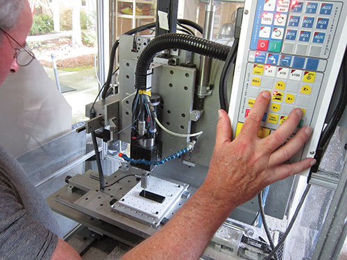
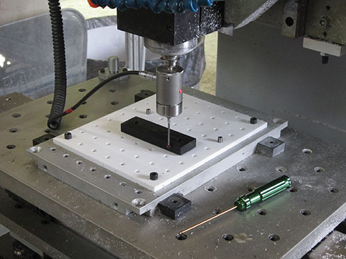
The industrial benchtop CNC mill that Dan Rosenthal installed in his garage is no toy. It has a range of optional features, including a 10-station ATC, 60,000-rpm spindle, toolsetting probe, touch-trigger probe and fourth-axis rotary table (not installed in this photo).
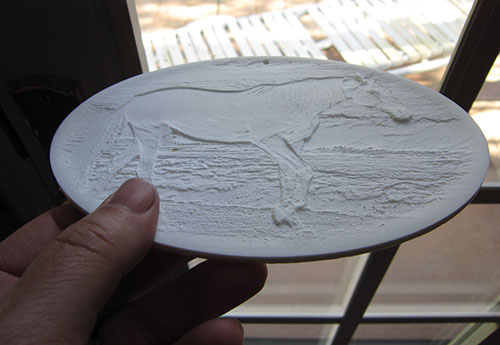
Mr. Rosenthal’s early personal milling projects included Corian plastic lithophanes like this one below that…
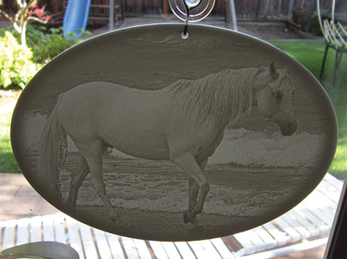
…come alive with backlighting.
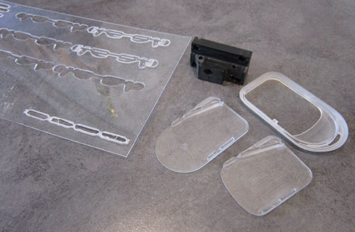
The parts shown here demonstrate the progression of project complexity for his single customer, starting with flat sheet and then moving to prismatic parts and parts with contoured surfaces. Intelligence built into the iMachining CAM software he uses has helped him ramp up to more challenging work.
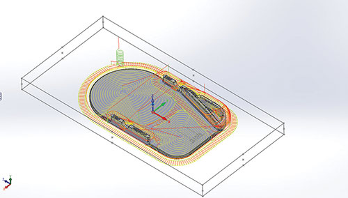
One signature feature in iMachining software is its “morphing spiral” tool path, which maintains a consistent load on the tool through consistent tool engagement.
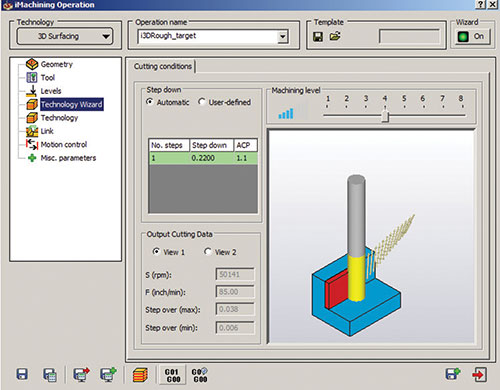
Another feature is the software's Technology Wizard, which uses application-specific information to determine the optimal cutting data for a job.
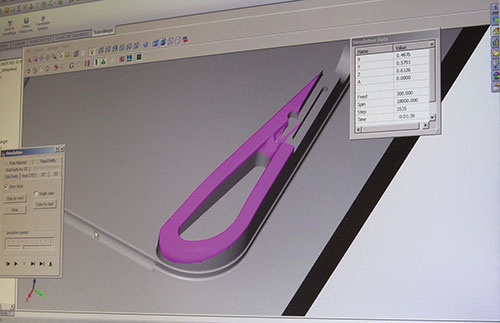
For parts like this with contours, Mr. Rosenthal will first rough with 3D iMachining and then use the High Speed Surfacing module to finish selected surfaces.
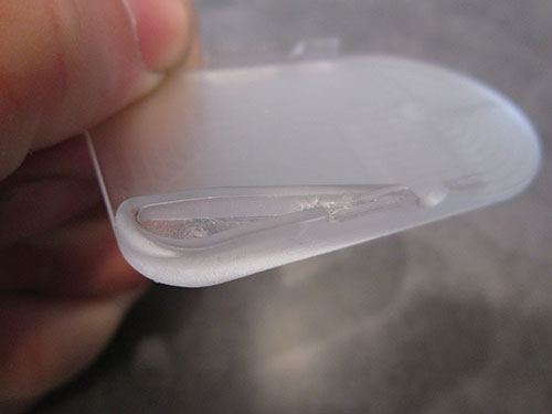
Here’s the machined part.
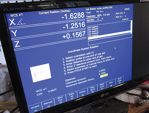
Canned cycles in the Centroid programming software enable easy probing routines for measuring tool length and part location on the table.
The latter determines the true location of a workpiece set up on the table and shifts the coordinate system to compensate. This eliminates the inherent challenge of accurately positioning parts using dial gages and traditional setup methods.
Mr. Rosenthal developed a strategy to simplify setups using expanding dowels installed in a Corian subplate. The dowels are used not only to locate the part on the table, but also to secure it for machining. He can also easily remove, flip and re-install the part to access its bottom surface.


Ten years ago, Dan Rosenthal retired from a successful engineering career and started a math tutoring business that continues to this day. His interests also turned to model aircraft as well as translucent artwork called lithophanes, which ultimately spurred him to purchase an industrial benchtop CNC mill two years ago to use at his Los Altos, California, home. The problem was, he had no machining experience whatsoever.
Today, Mr. Rosenthal’s skills have matured from basic 2D work in plastic sheet to parts having complex 3D contours. However, the prime driver of his improving skillset isn’t his hobby work. Rather, it is his sole customer, for whom he machines plastic prototypes. The customer has asked him to perform increasingly complex work, and this has enabled him to become more proficient at machining over the past couple of years.


That said, Mr. Rosenthal’s goal isn’t necessarily to establish a thriving machine shop business. Instead, he wants to establish a level of machining acumen that will enable him to create virtually any component his customer might request or he might need for his own projects.
But put aside the fact that Mr. Rosenthal uses a benchtop mill and might be considered a “hobby” machinist. His story is interesting in that it demonstrates how new machining technology—CAM in particular—is becoming more capable and easier to pick up and apply. So while his current goals might be different than that of a production-oriented shop, those shops can just as readily leverage the latest technology in the same way to grow the talent level of their existing workforce and bring new shopfloor hires up to speed more quickly.
Starting Machining
The more Mr. Rosenthal learned about lithophanes, the more he wanted to be able to machine them. Lithophanes are etched or molded artwork traditionally made from thin, translucent porcelain. They have what looks to be a rough image that comes alive with backlighting (see the horse photos to the left). He sought to machine these for friends and family from Corian plastic, and began looking for a CNC machine tool that would enable him to do that.
Clearly, machine size was a consideration, because it would reside in one bay of Mr. Rosenthal’s two-car garage (the other bay is reserved for his wife’s car). The CNC machine he purchased is an industrial benchtop unit from S&W Engineering that certainly is no toy. Mounted on a steel frame, it weighs 850 pounds and features a heavy-duty steel structure with a proprietary internal casting to minimize harmonic resonance and add structural integrity. Its X-, Y- and Z-axis travels measure 18 by 12 by 8 inches, and it was purchased with a number of options that brought its total cost close to $100,000. This includes a 60,000-rpm spindle to provide the speed necessary for small-diameter tools in balanced toolholders to perform detailed cuts in plastics and aluminum. He also ordered the machine with a 10-position automatic toolchanger, a touch-trigger probe, a tool-length measurement probe and an optional rotary table to enable four-axis machining (although he’s yet to use the rotary table). In addition, the machine has an air blast system, which is helpful for machining plastics, and an oil mist delivery system for aluminum parts.
Mr. Rosenthal first used the machine to create a number of lithophanes and other relatively simple personal machining projects. In 2013, however, he added his first and, at least for now, only customer: a venture capitalist acquaintance who learned about the machining work he was doing. His customer understood that he wasn’t a hugely skillful machinist at that time but decided to feed him some simple prototype work in plastic materials knowing he’d likely offer quicker turnaround than conventional shops that often don’t like to take on one-off-type work. Plus, the customer preferred machined prototypes over those printed via additive manufacturing because machined surfaces are smoother than the slightly stair-stepped finish additive equipment leaves behind.
Mr. Rosenthal says the CAM software he originally used was functional but still required him to make a number of choices related to cutting data. These choices would have likely been easy for a veteran machinist to make, but not for him given his limited experience. After some investigating, Mr. Rosenthal learned about iMachining CAM software from SolidCAM and purchased the company’s 2D iMachining module. He says what was important at that time was not necessarily minimizing programming or machining time, but rather generating tool paths that wouldn’t break the small-diameter tools he was using. What he particularly appreciated about the software was how he could leverage its built-in intelligence to generate effective tool paths based on machine and tool capabilities. Plus, it gave him an integrated CAD/CAM solution because he used Solidworks CAD software. This means he doesn’t have to leave the Solidworks environment to create the tool paths.
Intelligent Machining
The iMachining software has two signature features: its “morphing-spiral” tool path and Technology Wizard programming interface. The morphing-spiral toolpath motion is designed to maintain a consistent load on the tool through consistent tool engagement with the workpiece. The interior of the spiral motion is circular, while the outer portion conforms to the workpiece geometry being machined. During machining, the tool path “morphs” from the geometric contour to a pure circle or vise-versa, depending on whether the cut begins at the outer or inner portion of the spiral. For areas that can’t be cut with a single spiral, the software automatically subdivides that portion of the geometry, separating channels and tight corners. Each sub-area is then cut with its own spiral.
Morphing is possible because the software adjusts the stepover at various points along the tool path, using larger stepovers at thick points along the spiral and smaller ones at thin points. The software also uses stepover adjustments (within user-defined limits) to keep an equal portion of the cutter engaged in the material at all points along the tool path to maintain a consistent tool load. For instances in which thin areas of the spiral’s contour call for a lower stepover value that would otherwise cause a sudden decrease in tool load, the software automatically adjusts the feed rate to compensate. The software also considers workpiece geometry when plotting this motion to minimize air cutting and repositioning moves.
A proprietary algorithm automatically determines feeds, speeds, stepovers and cutting depths based on attributes entered into the Technology Wizard that are specific to the machine, such as spindle speed, power and rigidity. This information is entered just once during software setup and is also used to help create the postprocessor. A slider in the Technology Wizard can be used to adjust for machining aggressiveness on a scale of 1 to 8, which alters cutting data to achieve higher material removal while staying within the constraints of the machine and cutting tool. The algorithm then uses all that application-specific information to determine the cutting data for the job.
The 2D iMachining module worked well for the initial work Mr. Rosenthal did for his customer, much of this involving machining parts from plastic sheet. However, because the work he was being asked to perform was becoming increasingly complicated, progressing from prismatic parts to parts with complex contoured surfaces, Mr. Rosenthal decided to purchase the 3D iMachining module.
Like 2D iMachining, 3D iMachining uses the morphing spiral tool path to maintain consistent tool load while taking advantage of a longer portion of a tool’s flute. Successive, deep roughing passes are performed in downward steps, while rest roughing operations (when necessary) are performed at smaller upward steps. When Mr. Rosenthal added 3D iMachining, he also added SolidCAM’s High Speed Surface machining module (HSS). For most work, he uses 3D iMachining to perform the roughing operations, inputting the amount of excess stock that should be left for subsequent finishing of select surfaces using HSS. He can choose from a number of machining strategies in HSS to finish selected surfaces, such as surface machining with undercut, fillet machining, slotting, morp between two surfaces, morph between two curves and so on. HSS was used to create the contoured surface in the part shown in one of the images to the left.
Speeding Setups
Just as the CAM package Mr. Rosenthal uses has simplified programming, tool- and part-probing capability, using Centroid probes has proven extremely helpful (and also easy to apply) in streamlining setups for his low-volume prototype work. The tool measurement probe installed on the machine’s table enables automatic tool-length measurement after the proper probing routine is called up from the Centroid control software loaded on a dedicated PC near the machine. He can also install the touch-trigger probe into the machine’s spindle and use the control’s coordinate system rotation function to determine a part’s edge alignment when installed on a table. This establishes not only where the part is located on the table, but how it’s oriented. That way, it isn’t necessary to dial-in a part to ensure it is set up parallel to the machine axes.
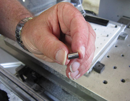
In fact, Mr. Rosenthal uses part probing capability as part of a standardized workholding method he developed using a Corian locator plate drilled with a grid of holes to accept DexLoc expanding dowels from Jergens. Shops commonly use these dowels simply to locate vises on a subplate, but the dowels serve as both locating and workholding devices in this application.
With a drilled Corian subplate installed on the table, the machine takes light facing cuts across the entire surface of the subplate. This leaves behind a subplate surface that’s normal to the machine’s Z axis, compensating for any variance in table levelness while creating a reference plane in the Z axis after the surface is probed. Next, a sawn blank, such as the one shown on in an image to the left, is probed to determine its X-Y center point, and then holes are drilled at the correct spacing to match two or more hole locations in the subplate. To secure the blank, Mr. Rosenthal inserts expanding dowels into the proper hole locations in the subplate. The top and bottom of these dowels expand separately, so he first uses a hand tool to expand the bottom of each installed dowel to lock it into the subplate. Next, the stock is dropped onto the dowels and the top of each dowel is expanded to secure the part for machining.
This workholding method provides adequate gripping force because the cutting loads are light for much of the work Mr. Rosenthal performs. Plus, it offers access to five sides of a part during machining, which wouldn’t be possible using conventional clamps. This enables him to accurately square sawn stock and machine a part from the middle of the stock (between the dowels). He can also easily remove, flip and re-install a workpiece to access its bottom surface. If holes for dowels have no impact on part design, Mr. Rosenthal can profile around the dowels, too.
What’s Next?
Between the CNC mill and air compressor on his side of the garage, Mr. Rosenthal has limited remaining floor space. However, he’d like to add a CNC turning center at some point. He also plans to add a four-axis machining module to his CAM package when he starts encountering parts that might be a good fit for machining using the rotary table he purchased.
That said, Mr. Rosenthal is still unsure where all this will ultimately lead. It may be that he’ll take on more work for his existing customer or add customers. My hope, though, is that he’ll strike a nice balance between performing work for others and himself, so machining remains less of a job and more of an enjoyable experience.


Related Content

How To Calibrate Your Calipers
If you’re interested in calibrating your own digital, dial or Vernier calipers, here are some steps to take to make sure it goes off without a hitch.
Read More
How to Choose the Correct Measuring Tool for Any Application
There are many options to choose from when deciding on a dimensional measurement tool. Consider these application-based factors when selecting a measurement solution.
Read More
Determining Out-of-Roundness at the Point of Manufacture
George Schuetz, Mahr Inc.’s Director of Precision Gages, offers these techniques for measuring roundness on the shop floor.
Read More
Building an Automation Solution From the Ground Up
IMTS 2022 provides visitors the opportunity to meet with product experts to design automation solutions from scratch.
Read MoreRead Next


3 Mistakes That Cause CNC Programs to Fail
Despite enhancements to manufacturing technology, there are still issues today that can cause programs to fail. These failures can cause lost time, scrapped parts, damaged machines and even injured operators.
Read More
The Cut Scene: The Finer Details of Large-Format Machining
Small details and features can have an outsized impact on large parts, such as Barbco’s collapsible utility drill head.
Read More