
Robotic Polishing of Turbine Engine Blades
Testing explores an airfoil finishing alternative to loose-abrasive polishing.
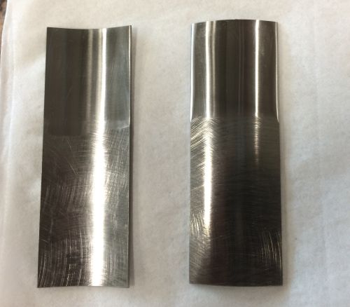
Ground test workpieces
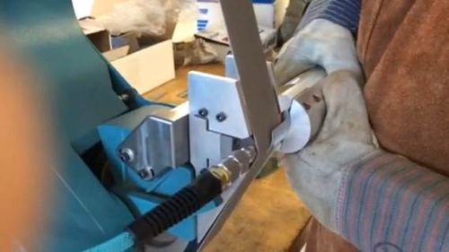
Figure 1: Concave side on modified platen
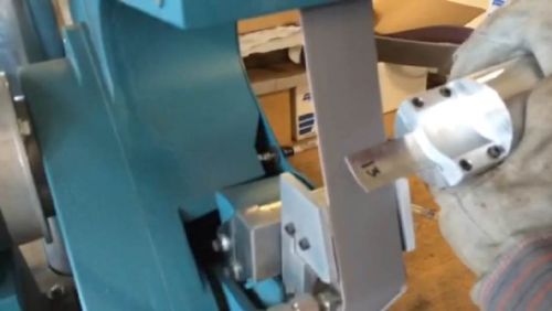
Figure 2: Concave side on slack of belt
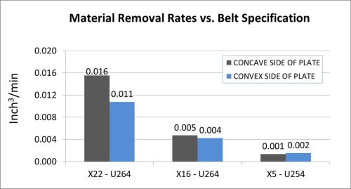
Figure 3: Material removal rates for each belt
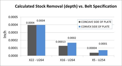
Figure 4: Stock removal for each belt
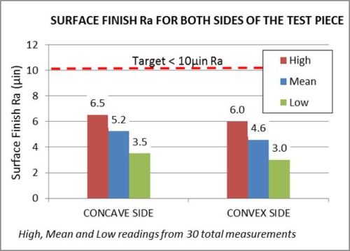
Figure 5: Surface finish Ra for both concave and convex sides
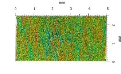
3D surface texture measurement after grinding using the X22 belt
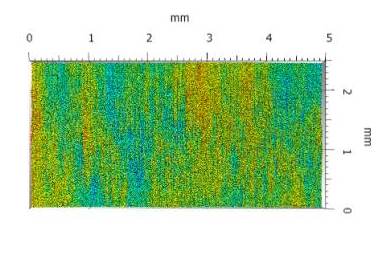
3D image of a workpiece that was finished using the X5 belt
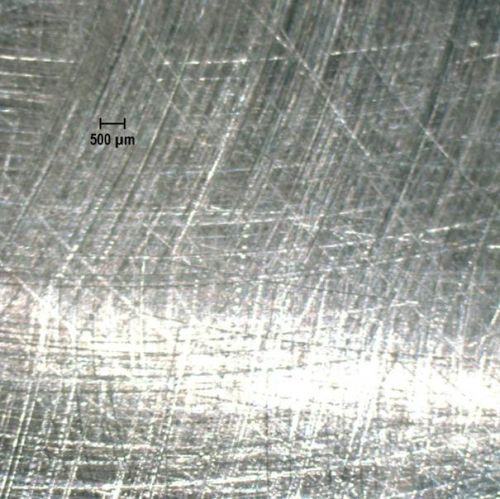
Magnified view of material before grind
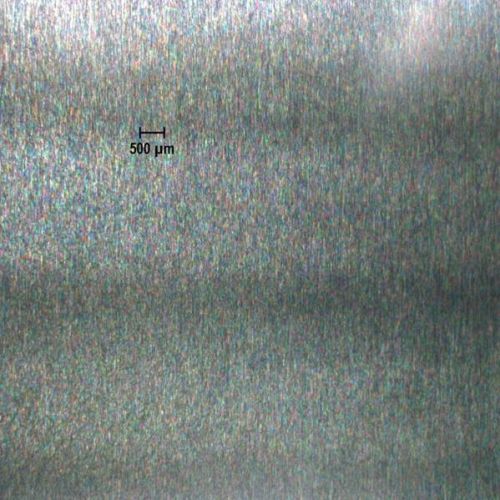
Magnified view of material after grind
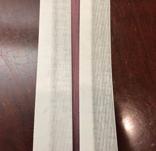
The belt used for the test. The darker sections are the used portion of the abrasive face.
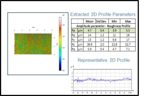
3D surface measurement of one of the parts finished using the process outlined in this paper


Robots provide many advantages over manual operations for material removal processes such as grinding, finishing, deburring, and polishing. Manual material removal operations run the risk of possible operator fatigue and injury and associated part inconsistencies. In addition, manual operations can prove to be time-consuming and involve costly labor. Often due to the tediousness of these manual removal processes, companies find it extremely difficult to replace personnel trained in these operations after they leave. Robotic operations on the other hand face none of these challenges and in most cases can improve cycle time and reduced scrap rate when compared to manual operations. It is for these reasons that robots have been increasingly implemented for these processes.
Like this article? See more every month.
Subscribe to Modern Machine Shop.
Abrasive products currently used in these robotic material removal operations often are not very different from those used in manual operations. However, the growth in robotic manufacturing is providing an impetus to the development of abrasive products that are custom-made for robotic material removal. Robotic material removal applications require abrasive products that provide consistent cut-rate, predictable wear, necessary compliance and conformance to the part or the component being abraded. Keeping these characteristics in mind, engineers and application specialists at Norton Saint-Gobain Abrasives have been testing and developing abrasive products for acceptance in robotic material removal applications.


In addition to having the right product, an understanding of the physics of the process for robotic deburring or polishing is also important for success. Loose abrasive polishing has been used since ancient times to achieve the final surface finish specifications and aesthetic appeal on components. For aerospace components such as blades and blisks, loose abrasive polishing typically is done through processes such as chemical vibratory polishing or abrasive flow machining. Even though these loose abrasive processes are still very common, they suffer from disadvantages such as low efficiency due to long set-up and cycle time, high waste of materials and pollution to the work environment. With these processes it is also difficult to control the form and accuracy of complex features on components by maintaining uniform cutting or polishing action, since the media is in a loose state. Therefore a fixed abrasive solution that eliminates these disadvantages would often be preferred. However, with fixed abrasive processes there are two challenges that need to be overcome before they can be successfully implemented for automated polishing. The first challenge is that these components have fine and/or complex features that need to be accessed by the fixed abrasive media such as the belt or grinding wheel. So part geometry and precise robotic programming to ensure maneuverability and access to all areas of interest on the part becomes critical. The second challenge is to avoid over-cutting or excess stock removal is achieving the finish and cosmetic specifications on a component. Norton Saint Gobain Abrasives has done numerous projects at its state-of-the-art Higgins Grinding Technology Center (HGTC) for providing fixed abrasive solutions for polishing aerospace components. This article presents the results of one such recent study done at the SGA laboratory in Worcester, Massachusetts, to determine the effectiveness and applicability of engineered abrasives on contoured work parts made of Inconel 718.
The test methodology was designed around the goal of polishing the airfoil surfaces of turbine engine blades to achieve finishes less than 10µin Ra. The test bed that was used was a Dynabrade bench top sander with a modified platen that matched the curvature of our work pieces. The 718 Inconel workpieces were bent to emulate a simple curvature for both the concave and convex sides of the airfoil. The concave portion of the workpiece was polished using an abrasive belt riding over the modified platen (Figure 1), while the convex side was polished using the conformance of the “slack of belt” (Figure 2). The abrasive media of choice were a variety of Norton NoRax belts which fall into the category of engineered abrasives. NoRax is an engineered, 3D coated abrasive product that offers high performance in terms of consistent cut rate and predictable wear characteristics in addition to fine finishing capabilities.
The workpieces were weighed before and after each grind and the contact time recorded, allowing for the cut rates to be calculated. Knowing the amount of material removed allowed for an approximate depth of cut calculation, using the contact area and the material density. While this is an approximation, it is valuable information when dealing with the tight tolerances in aerospace applications. Once a belt sequence was determined through some initial trial and error, the surface finishes were recorded before and after polishing using a profilometer and a profile scan. The resulting data showed promise. The belt sequence chosen for the testing was as follows:
- U264 X22
- U264 X16
- U254 X5
This sequence was used for both the concave and convex sides of the work piece and was repeated on 10 pieces. The cut rates declined (Figure 3) with the finer grits, as to be expected, and this is an indication that the majority of the deeper scratches on the incoming work piece are being removed by the U264 X22. The depths of cut were minimal, which is desirable in a polishing application where overgrinding can be a concern (Figure 4).
Surface finish Ra was measured using a contact stylus profilometer. Measurements were taken both parallel and perpendicular to the grind lines (texture lay). All measured values were very similar, regardless of measurement direction. As shown in Figure 5, the mean values were calculated to be 5.2 µin Ra on the concave side of the workpiece and a mean of 4.6 µin Ra on the convex side. The highest and lowest readings measured were 6.5 and 3.5 µin Ra for the concave side and 6.0 and 3.0 µin Ra for the convex. All readings were well below the target 10 µin Ra.
In a belt grinding operation the lay (grind lines) will typically be orientated in a single direction. The lay direction is produced based on the orientation of the belt as it contacts the workpiece. As a result of these grind lines, the surface roughness when measured perpendicular to the lay is typically greater than when measured parallel to the lay. Whereas, in loose abrasive applications such as chemical vibratory polishing, the surface finish achieved has a lay that is multi-directional. Therefore the surface finish is typically the same irrespective of the measuring direction. In this study, when utilizing the coarser belts the grind lines were evident and the surface measurements in the perpendicular direction were indeed greater than measured in the parallel direction. However by starting with the coarser grit X22, followed by the X16 and then finishing using the finer grit X5 abrasive, the grind lines were reduced to such an extent that parallel and perpendicular surface finish measures were the same. This shows that by using the process outlined in the paper it is possible to produce a non-directional lay on Inconel 718 material, very similar to a loose abrasive process.


Related Content

Volumetric Accuracy Is Key to Machining James Webb Telescope
To meet the extreme tolerance of the telescope’s beryllium mirrors, the manufacturer had to rely on stable horizontal machining centers with a high degree of consistency volumetric accuracy.
Read More
10 Things to Know About Creep-Feed Grinding
Because of the high material removal rate creep-feed grinding can deliver in challenging materials, grinding might not be just the last step in the process—it might be the process.
Read More
Choosing The Right Grinding Wheel
Understanding grinding wheel fundamentals will help you choose the right wheel for the job.
Read More
A New Milling 101: Milling Forces and Formulas
The forces involved in the milling process can be quantified, thus allowing mathematical tools to predict and control these forces. Formulas for calculating these forces accurately make it possible to optimize the quality of milling operations.
Read MoreRead Next

The Cut Scene: The Finer Details of Large-Format Machining
Small details and features can have an outsized impact on large parts, such as Barbco’s collapsible utility drill head.
Read More

3 Mistakes That Cause CNC Programs to Fail
Despite enhancements to manufacturing technology, there are still issues today that can cause programs to fail. These failures can cause lost time, scrapped parts, damaged machines and even injured operators.
Read More