
The Overhang Effect
The length by which the tool extends from the toolholder is a variable that can be used to 'tune' the machining process. Contrary to what you may expect, increasing the tool's L:D ratio may reduce chatter and result in more productive milling.
.jpg;width=70;height=70;mode=crop;format=webp)


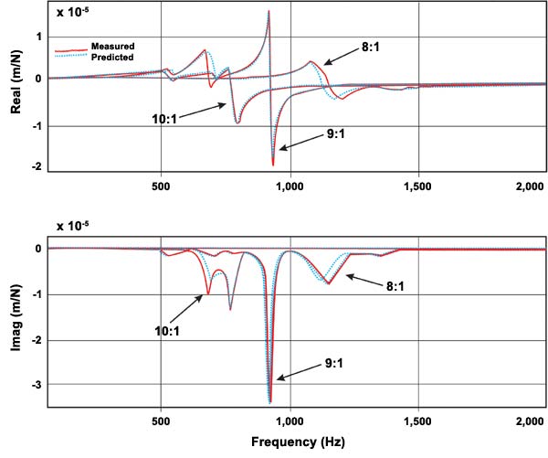
Fig. 3—Some engineers may recognize these graphs as the “real” and “imaginary” components of a frequency response plot, but understanding what that means is not necessary here. The graphs represent the tendency to chatter when the same tool was used at different overhang lengths in a given application. A larger amplitude means the tendency to chatter is greater. The graphs show that increasing the overhang length increased the tendency toward chatter in the move from an L:D ratio of 8:1 to 9:1. However, the trend reversed itself in the move to 10:1, a more stable overhang value.
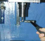

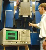
Fig. 1—A “tap test” measures the frequency response of a particular system of spindle and tooling. The frequency response suggests the most stable speeds for milling. Here the test is demonstrated by Mike Tummond, a University of Florida graduate student. Machining researcher Tony Schmitz hopes one day to see a Web-based utility that can overcome the need for a shop to perform such testing.
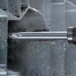
Photo courtesy Ingersoll Milling Machines
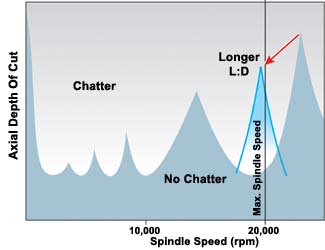
Fig. 4—Increasing the overhang length tends to move the stability peaks down and to the left. That is, the stable speed decreases to a lower value, and so does the corresponding maximum depth of cut. This effect is useful if it can capture a sweet spot that used to lie beyond the top speed of the spindle, thereby bringing it down to just within the spindle’s range.
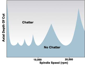
Fig. 2—This diagram illustrates the relationship between speed and depth of cut for a particular system of tool, toolholder and high speed spindle. For any such system, the upper portion of the spindle’s speed range can be expected to offer one or more “sweet spots” where significantly deeper cutting is possible.
High speed machining can require adjustments to the process that are counter-intuitive. When chatter occurs, the natural reflex is to reduce spindle speed, but increasing the speed may in fact be a more productive response. Another common response to chatter is to switch to a tool with a smaller length-to-diameter ratio, because of the seeming stiffness of a shorter tool. In certain cases, however, a tool that reaches farther will deliver a superior cut.
The first of these phenomena, the relationship between chatter and speed, is understood by a fair number of shops, including some who routinely put the knowledge to use. Every distinct combination of spindle, toolholder and cutting tool represents a particular dynamic system that has its own inherently stable signature frequencies. Mill so that the rate of cutting edge impacts comes close to matching one of these resonant frequencies, and the tool can cut smoothly at a depth of cut that is heavier than what would be possible at either a faster or a slower speed. Shops that have discovered what these “sweet spots” are for their own processes don’t back off the spindle speed to avoid chatter; they run at the fastest stable speed available to achieve a high rate of material removal.


But there is also a relationship between chatter and tool overhang, and this relationship is not as well appreciated. Tool overhang is defined here as the length by which the tool extends from the holder. Collet and shrink fit holders (among others) offer some freedom to vary the overhang length. This variable can allow shops that are already performing high speed machining using inherently stable spindle speeds to achieve greater productivity still.
One limitation of machining at the stable speeds is that the maximum speed of the process is typically unused. The greatest metal removal rate instead comes at the maximum stable speed, because of the much greater depth of cut permissible here. The top speed and top stable speed are two different values. But this doesn’t have to be so. Changing the tool overhang length changes the overall system, and therefore changes the signature frequencies. So why not “tune” the system by selecting the precise tool overhang that causes a sweet spot to fall at the maximum speed of the spindle?
One researcher who has worked to develop this method of tuning the machining process is Tony Schmitz, an assistant professor with the University of Florida’s Machine Tool Research Center. Dr. Schmitz refers to this tuning as “receptance coupling substructure analysis.” The institution for which he works is a center for high speed machining research, offering a laboratory that includes an Ingersoll High Velocity machining center among other resources.
To determine the optimal tool overhang for a given application, Dr. Schmitz performs a “tap test” similar to what certain shops perform to find their own optimum speeds. (See Figure 1.) This test involves a sensor affixed to the combination of machine and tooling that makes up the machining system, along with a delicate hammer for tapping this system and an analysis tool for measuring the frequency response. Dr. Schmitz performs this test first without a tool in the holder. A second test evaluates the stiffness and damping in the connection between the holder and tool. With this much known, the tool itself is simple enough that its contribution to the frequency response can be modeled mathematically. Armed with all of this information, Dr. Schmitz can calculate the specific overhang length that will allow this particular system to take deep cuts without chatter near the spindle’s maximum rpm.
The professor readily acknowledges that only a small number of shops today know how to tap-test their machines, and fewer still have access to the vibrations expertise necessary to calculate optimum overhang lengths. However, his study of tool tuning in various applications suggests a generalization about when to increase tool length that doesn’t require a mathematical understanding. The insight can help those shops that are currently taking advantage of low-chatter speeds, and it may be of help to any shop that struggles to combine high spindle speed with a high ratio of L:D.
Sweet Spot Basics
The shops that understand how to run at low-chatter speeds today tend to serve the aircraft industry. There are a variety of reasons for this. These shops machine aluminum, a material that makes it practical to use aggressive speeds and aggressive depths of cut at the same time, provided the process can achieve these two parameters at once. Also, aerospace shops tend not to be blessed with a long run of parts that can allow them to fine-tune the process experimentally, so they need to do their fine-tuning through analytical means instead. All of that said, there is nothing about chatter or the method of transcending it that has anything inherently to do with aircraft parts or aluminum machining. Resonant-frequency machining is potentially relevant to any application featuring a moderate to heavy depth of cut and a high spindle speed (and can even be relevant to some not-so-high-speed processes as well).
“Chatter,” in the context of this machining, refers to self-excited vibration. Every combination of spindle and tooling has a certain characteristic set of resonant frequencies at which the system inherently wants to vibrate. These frequencies leave their mark on the workpiece in the form of surface waviness. By means of this waviness, a milling pass interacts with the pass that preceded it. Because the cutting edges hit at various points along the crests and valleys of the waves, the chip thickness varies from one cutting edge to the next. Chatter is the result of this variation in load, and its severity worsens as the nominal depth of cut is increased.
But there is a way to bypass chatter. At certain high speeds—beyond 10,000 rpm for certain spindle-and-tooling systems, beyond 15,000 rpm for others—the rate of cutting edge impacts can come close to matching one of the resonant frequencies of the system. When this occurs, the process can be said to harmonize. Smooth machining becomes possible at significantly heavier depths of cut, because the cutting action synchronizes with the pattern of surface waviness.
Figure 2 illustrates the consequence of this phenomenon. The diagram represents the way that the allowable depth of cut varies across the available speed range for a typical process. The peaks indicate the sweet spots where stable machining is possible at distinctly heavier depths. Shops that are aware of these sweet spots often prefer to run at one of these speeds, because the resonant speed can offer considerably higher productivity. Instead of running a 20,000-rpm spindle at 20,000 rpm, in other words, the shop runs at some predetermined stable speed such as 17,260 rpm. The stable speed is slower, but the corresponding depth of cut is larger by comparison, resulting in a metal removal rate that is higher overall.
And yet the need to choose one speed or the other points out where there is room for further improvement. An ideal process would make it possible to perform stable cutting at the spindle’s top rpm. Tool tuning offers a way to zero in on this ideal process.
Tool Tuning
One of Dr. Schmitz’s applications of this tuning involved an aircraft structural part with pockets more than 100 mm deep. To reduce this part’s weight, it was necessary to remove material from the pockets’ corners. The long, skinny end mill that was needed for this job (“wet noodle” tooling, says Dr. Schmitz) was highly susceptible to chatter.
The engineers involved with this project tried different overhang lengths, each one run at the top spindle speed, without changing anything else about the process. At an overhang of 8 times diameter, the tool chattered. At 9 times diameter, the tool chattered even more. But at an overhang of 10, something unexpected occurred. The longer tool extension ran with less chatter, because this overhang length just happened to shift a sweet spot close to the spindle’s top speed. (See Figure 3.)
The study of tool overhang in this and other applications has made it possible to offer certain general statements about its effects.
If an overhung tool is chattering, will less overhang reduce the chatter? Most would expect that the answer is yes. Dr. Schmitz says the answer is only probably yes. A shorter tool length is usually more stable, but in some cases stability improvement can come from making the tool longer.
Can a shop predict when the longer tool length is called for? Without modeling, he says, there is no way to know for certain. However, a particular indicator does provide grounds for suspicion. If the top speed for stable cutting is far removed from the top speed of the spindle, that’s a clue to try a longer overhang length.
For example, if the spindle is capable of 20,000 rpm, but an inherently stable sweet spot occurs around 13,000 rpm and no closer to the top speed than that, then experimenting with longer overhang lengths is potentially worthwhile. The right increase in overhang length may make the process considerably more productive.
Again, changing the overhang length changes the overall system, and therefore changes where the sweet spots lie. But more specifically, increasing the overhang length tends to shift the sweet spots to lower speeds.
This downward shift would normally hurt productivity instead of helping it. However, in the case of the 20K spindle with the 13K sweet spot, the long gap with no resonant frequency suggests there may be another resonant frequency of the system waiting just beyond the maximum cutting frequency that the spindle can obtain. Increasing tool overhang will tend to bring down this out-of-reach frequency, possibly to within the spindle’s range.
Figure 4 illustrates this. Thanks to the use of a longer tool, the stable zone that used to be out of reach has moved to the left, bringing this region down into the process’s speed range. Now the system can take smooth, deep cuts near 20,000 rpm instead of near 13,000 rpm.
At the same time, the “peak” of this stable zone—the maximum allowable depth of cut—has shifted lower. This shift illustrates one caveat about tool tuning. Increasing tool length reduces not just the rpm value for stable cutting but also the depth of cut (because the tool is now more flexible). In the case of the hypothetical spindle, however, stable cutting around 20,000 rpm stands to be more productive than cutting around 13,000 rpm, even if the depth of cut is reduced.
A more significant caveat comes from the fact that increasing tool overhang only TENDS to shift the sweet spots lower. The phenomenon of stability peaks moving down and to the left operates only within a narrow range. Changing the overhang length may also have an effect comparable to reshuffling the deck. If the change in overhang moves the tool’s own natural frequency close to one of the spindle’s natural frequencies, the result may be an entirely new distribution of stable speeds, with the tooling, spindle and overhang length all settling into different relationships with one another.
Case Study
Dr. Schmitz recounts a particularly dramatic application of tool tuning involving a milling application in nickel aluminum bronze with a 24,000 rpm, 70 kW spindle. The application permitted an overhang length in the range of 107 to 127 mm.
One of the tools tested was a 19-mm-diameter, four-flute bull-nose mill. At the minimum overhang, smooth cutting occurred at 14,680 rpm, with a corresponding depth of cut of 1.6 mm for a full-slot cut. (Running at the top spindle speed with this overhang allowed a depth of cut of only 0.2 mm.)
Extending the tool to its maximum overhang lowered the top speed for stable cutting down to 11,820 rpm. The depth of cut fell to 0.9 mm. The shorter overhang was clearly more productive.
However, using a tool with only two flutes at the maximum overhang was shown to permit stable cutting at 23,640 rpm—very close to the top speed of the spindle. The achievable depth of cut at this speed was 1.8 mm.
In other words, the tool that had fewer flutes matched the metal removal rate of the tool that had more flutes—and did so with the added benefit of allowing a longer tool overhang.
The Tuning Utility
The efficiency of this counter-intuitive choice in tooling was discovered mathematically, not by sampling tools through cutting trials on the machine. The typical machine shop’s inability to perform this modeling—not to mention the small number of shops equipped to perform frequency-response measurement on their machines—presents a serious obstacle to the practice of tool tuning entering into widespread use.
However, Dr. Schmitz sees a resource that could overcome this obstacle. A Web-based utility could draw on a database of frequency-response measurements for various spindle-and-toolholder combinations, along with mathematical models for various tool designs. This would allow a user simply to enter the basic parameters of a given application to receive the optimum low-chatter speed and depth-of-cut values in return. The utility would make it easy for any production employee to experiment with tool types and tool overhang lengths to determine what combination will provide the very best performance.
To develop such a resource, researchers would visit major spindle makers and machine tool builders, performing tap tests on each of their standard spindle designs with various toolholder types loaded in the spindle. Researchers would also model the various milling tool designs most likely to be required for high speed machining applications.
The amount of work would be significant but manageable, Dr. Schmitz says. He hopes to see this resource developed at the university where he works, and he hopes to oversee its development himself. He is currently searching for the support necessary to make this idea real.
Tony Schmitz can be contacted at tschmitz@ufl.edu.
Dr. Schmitz wishes to acknowledge the early researchers into tool tuning responsible for recognizing and developing this phenomenon. They include Dr. Bob Winfough, Dr. Scott Smith, Mr. Jerry Halley, Dr. Matthew Davies, Dr. Jon Pratt and Mr. Brian Dutterer.


Related Content

10 Tips for Titanium
Simple process considerations can increase your productivity in milling titanium alloys.
Read More
The Impact of Cutting Teeth Spacing on Machining Stability
Many cutter designs are available, and variable teeth spacing (or variable pitch) cutters can be used to influence milling stability. Let’s discuss why teeth spacing affects stability.
Read More
A New Milling 101: Milling Forces and Formulas
The forces involved in the milling process can be quantified, thus allowing mathematical tools to predict and control these forces. Formulas for calculating these forces accurately make it possible to optimize the quality of milling operations.
Read More
Grooving Attachment Streamlines Operation by 75%
A grooving attachment enabled Keselowski Advanced Manufacturing to reduce cycle times by over 45 minutes on a high-value, high-nickel part feature.
Read MoreRead Next

Maximum Aluminum: Optimizing Metal Removal Rate in Aluminum with a High Speed Spindle
Speed changes the rules. To maximize metal removal rate with a high speed spindle, follow some fundamental tooling considerations and mill at just the right rpm.
Read More
3 Mistakes That Cause CNC Programs to Fail
Despite enhancements to manufacturing technology, there are still issues today that can cause programs to fail. These failures can cause lost time, scrapped parts, damaged machines and even injured operators.
Read More
The Cut Scene: The Finer Details of Large-Format Machining
Small details and features can have an outsized impact on large parts, such as Barbco’s collapsible utility drill head.
Read More