The Role Of Balance In High Speed Finish Boring
Precision boring is particularly vulnerable to unbalance, but not every high speed boring application demands a balanceable tool.
.jpg;width=70;height=70;mode=crop;format=webp)


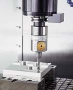
On this finish boring tool, the gold-colored dial is used to change the cutting diameter. Compensating for the resulting unbalance is the purpose of the silver dial that follows the tool's circumference. Moving this dial moves a counterweight mechanism located inside the body of the tool.
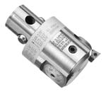
Fig. 2—The finish boring tool shown here is balanced at a diameter setting near the middle of its adjustable range.
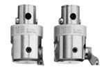
Changing the insert holder attachment increases the cutting diameter and also increases unbalance.
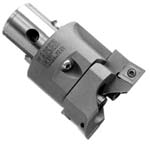
Fig. 3—This rough boring tool uses opposing inserts to balance cutting forces, minimizing deflection during cutting.
A single-point boring tool with adjustable cutting diameter may be used for the tightest-tolerance cutting that a given machining center is likely to perform. At the same time, this tool is probably the most inherently unbalanced object the machine will ever use to take a cut.
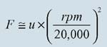
This irony has real consequence as spindle speed increases, because the centrifugal force resulting from unbalance increases as the square of rotational speed. Raising the speed from 4,000 to 8,000 rpm, without any change in tooling, causes centrifugal force to quadruple. Raising the speed of the same process to 12,000 rpm raises the force from unbalance to 9 times what it was at the original speed. Because of the exponential increase, an effect that was once negligible may be amplified to the point that tight tolerances can no longer be held.


One company providing variable-diameter precision boring tools is KPT Kaiser of Elk Grove Village, Illinois. During the past decade, as maximum spindle speeds for all classes of machining centers were increasing significantly, this company introduced updated versions of its tools better suited to boring at high rpm. Among the newer versions are adjustable-balance models that use moving counterweights to compensate for the change in unbalance that comes from changing the radial position of the cutting insert.
But not every boring application—not even every high speed application—is a candidate for one of these balanceable tools. Vice president of engineering Jack Burley says that tools with adjustable balance account for only 10 percent of the company's sales of the variable-diameter tooling. Tools that are not balanceable by means of a moving counterweight are nevertheless engineered to be balanced at the middle of the tool's adjustable diameter range. And for most finish boring applications, just this level of balance is enough.
Understanding unbalance as it applies to single-point boring is useful for shops that want to machine precision holes at faster cutting speeds. In addition, the same understanding is also useful in a larger context. Shops moving to higher spindle speeds for various applications are often concerned about the potential effects of unbalance. The example of high speed finish boring, which combines a highly asymmetric tool with a very light depth of cut, can provide a useful benchmark for these shops. The extreme set of conditions shows the extent of the impact that unbalance can have on the performance of the process.
Mr. Burley says a common mistake in high speed machining is to give too little consideration to balance. Another common mistake, he says, is to give too much consideration to balance. Higher speeds do make it worthwhile to use high-quality tools and toolholders manufactured to tight balance requirements, but where end mills and other inherently symmetrical tools are concerned, just choosing quality tooling is probably enough to ensure that balance is sufficient. Trying to improve balance further through some off-line adjustment to the tool is likely to be overkill, resulting in a change in centrifugal force that's tiny compared to the force from the cut. The reason is that single-point boring tools are more prone to require balance adjustment precisely is that the light depth of cut makes a small unbalance force more significant by comparison.
And even at that, the effect of unbalance would not be considered significant to everyone. Comparison testing at 10,000 rpm between balanceable and non-balanceable single-point tools showed a difference in hole roundness error of about 5 microns (see Figure 1). Many machining operations could tolerate error of a comparable magnitude. But in precision boring, error of this magnitude has to be addressed.
Boring And Speed
An example of an adjustable-diameter finish boring tool is shown in Figure 2, below left. The adjustability allows this one tool to machine a variety of different hole diameters.And the fineness of the adjustability lets the tool zero in on a precise diameter by compensating for differences in deflection from machine to machine or from setup to setup. Toperform this compensation, the tool is generally run through two passes when it's used within a particular process for the first time. The first pass is taken at a slightly undersize diameter. The bore is measured after this cut. The tool's diameter is then increased by the amount necessary to remove the stock envelope that remains.
This tool finishes holes for which an acceptable location accuracy, roundness and straightness have already been established. A rough boring tool used to establish these parameters is shown in Figure 3, below right. The diameter of this tool is also adjustable, but not with the same fine control. This tool machines pre-existing holes such as the cored holes in castings and forgings. Hole roundness and straightness result from the tool's design, which positions the cutting inserts so that their cutting forces directly oppose one another. Other tools used to rough out holes don't feature the same complementary forces, and the lack of equilibrium can affect hole geometry. A drill, for example, tends to walk. An end mill used for circular milling has a tendency to deflect away from the cut that increases as the tool gets longer. The rough boring tool's balance of forces overcomes these problems.
With this tool, the benefit of using a higher speed is simple productivity. Unbalance is no cause for concern because the tool doesn't take precision cuts, and because the symmetry of the tool tends to limit unbalance to a level small enough that it doesn't affect performance.
With the finish boring tool, on the other hand, the benefits of using a higher speed are more numerous. And the challenge posed by unbalance is greater.
High speed in finish boring increases productivity, but it can also improve bore quality. The higher-end cutting tool materials such as PCD, CBN and ceramic (see Figure 4) can generate a smoother surface as cutting speed increases. In addition, faster cutting can translate directly to reduced tooling costs, because these same tools achieve longer life at higher speeds.
The potential obstacle to realizing all of these benefits is the centrifugal force from unbalance.
Balancing Action
The balanceable version of the adjustable-diameter tool shown in Figure 2 makes its balance correction automatically. Inside the body of the tool, mobile counterweights move in unison with any change to the cutting diameter.
More complex is the balance correction required for the finish boring tool shown in the photo at the beginning of this article. With this extended-reach tool, the diameter adjustment is not the only variable affecting unbalance. Also significant is the user's choice of extension length.
To compensate for this mix of variables, the tool uses a manual balancing system. A numbered dial moves the counterweight mechanism inside the tool's body. The dial's numbers refer to a chart from the tool manufacturer. On this chart, the user looks up the intended bore diameter and bore depth, along with the nose radius of the cutting insert, to determine the correct setting for the counterweight dial.
There are many other factors than these that also contribute to unbalance. How tightly the extension is screwed on will also affect the tool's balance condition. So too will the choice of insert, because a cermet insert weighs one half as much as the same insert made of carbide. With the adjustable-balance tool, influences such as these are not compensated.
But then, the objective in balancing this tool is not to meet some narrow balance target. The goal instead is to reduce unbalance to the point where a stable cut is possible because the cutting force is much larger than the centrifugal force. Beyond this point, further improvement would not noticeably affect the amount of force that the workpiece or the machine tool sees while the tool is cutting. The most important "balance," in other words, is the balance struck between the amount of process improvement that is possible and the amount of improvement that is sufficient for the needs of the application at hand.


Related Content

Emuge-Franken's New Drill Geometry Optimizes Chipbreaking
PunchDrill features patent-pending geometry with a chipbreaker that produces short chips to control machining forces.
Read More
10 Ways Additive Manufacturing and Machining Go Together and Affect One Another
Forget “additive versus subtractive.” Machining and metal additive manufacturing are interconnected, and enhance the possibilities for one another. Here is a look at just some of the ways additive and machining interrelate right now.
Read More
Form Tapping Improves Tool Life, Costs
Moving from cut tapping to form tapping for a notable application cut tooling costs at Siemens Energy and increased tool life a hundredfold.
Read More
How to Tackle Tough Angled Pocket Milling With Two Tools
Milling a deep pocket with a tight corner radius comes with unique challenges, but using both a flat bottom drill and a necked-down finishing tool can help.
Read MoreRead Next

Should You Balance Your Tools?
The answer varies from process to process. Experience is the best guide.
Read More
The Cut Scene: The Finer Details of Large-Format Machining
Small details and features can have an outsized impact on large parts, such as Barbco’s collapsible utility drill head.
Read More
3 Mistakes That Cause CNC Programs to Fail
Despite enhancements to manufacturing technology, there are still issues today that can cause programs to fail. These failures can cause lost time, scrapped parts, damaged machines and even injured operators.
Read More