Turning Wheel Hubs? Think About More Than Just Turning
Automotive suppliers are today being asked to supply wheel, brake and suspension components to ever-tighter tolerances. To accomplish this, single suppliers are taking responsibility for delivering more than turned blanks. They take more control of the process by performing turning, gauging, testing and assembly—on demand. Here’s one shop’s approach.


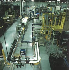
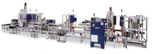
This hub line at Simpson Industries’ Edon, Ohio, facility has more than 445 feet of conveyor moving front and rear wheel hubs across 25 stations.
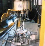
A U.S. drill head machine creates holes for the wheel hub studs to be pressed into. The multi-tool head drills all five holes in a single stroke.
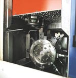
This is one of three Hessapp vertical turning centers installed in the hub line. This inverted spindle design eliminates the need for auxiliary spindle load/unload equipment.
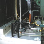
Driven hubs require a spline bore. This operation is carried out by vertical broaching as shown here.
The system’s integrator, Novi Precision, designed this non-synchronous knuckle assembly machine. Production is 1,000 flawless assemblies per day.
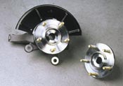
These are completed front and rear hubs with studs installed. Demand for complete assemblies is driving automotive suppliers to be responsible for more than just machined parts.
That automobile manufacturers have been doing less and less manufacturing, pushing this down onto their suppliers, and have become essentially “assemblers” of vehicles comes as no surprise. In fact, as a trend, this has been going on so long that the word “trend” is no longer applicable.
What is noteworthy, however, is the degree of responsibility being pushed down and the increasingly broad range of technologies in which suppliers are being asked to become proficient. Take the Simpson Industries, Inc., facility in Edon, Ohio. The supplier makes front and rear wheel hubs and knuckle assemblies for a new breed of sport utility vehicles (SUV) being brought to market in the near term.


To achieve the tolerance demands and quality standards necessary, Simpson has created a process-based system that significantly improves the total tolerance band of an assembled component. By tightly controlling individual parts, the assembled component will be in tolerance. Here’s a look at the system the company has installed to do this.
“Turnkey” Not What It Used To Mean
The installation at Simpson is a complex, sophisticated turnkey designed and installed by Novi Precision Products, Inc., with much of the technology sourced through KAR Enterprises, Inc. (both of Brighton, Michigan).
What Simpson wanted was a turnkey supplier to provide a system that would allow the company to go from rough castings and forgings to finished front and rear wheel hubs and hub and knuckle assemblies. The system needed to include the machining and all related processes—ultimately utilizing as few operators as possible (How about no more than eight?) and taking full system management responsibility as well.
Sound like a tall order? John Goit, vice president, engineering, Novi Precision, says that the project has been significant and not without challenge. “But,” he says, “what’s truly unique is that we’ve managed everything—supplied the lathes, the broaches, the drilling machine, the assembly equipment, the gages and all the automation connecting everything together.”
“It’s unusual for one company to supply almost everything and manage the overall project. It’s what we and KAR Enterprises call Complete Process Development Procurement (CPDP), which is changing and redefining the concept of turnkey manufacturing systems. The days of a company like Simpson Industries bidding out portions of a system and then integrating them are over,” Mr. Goit says. “Today companies expect to turn to a single source for system design, specification of the tools and technology, installation and final part run-off. And they expect the best, in technology and technical support.”
Turning And Then Some
Jeff Herman, manager of process control at Simpson, lives with the turnkey everyday. He knows what’s gone smoothly and what hasn’t, and he’s quite willing to talk about it.
“There’s a heck of a lot going on in relatively tight space—about 20,000 square feet,” he says. In wrestling with a description of how the turnkey works, one place to start, he says, is with turning the wheel hubs. It’s the first operation of some 25.
“We do front hubs and two varieties of rear hubs—one driven and the other non-driven. Right now, the demand for non-driven hubs is about 25 percent of that for driven, which just tells you that there’s going to be an increase in four-wheel drive SUVs on the road.”
Basically, there are two nearly identical turning lines, one for front wheel hubs and the other for rear hubs. Each has three Hessapp 150 DUO vertical CNC lathes with moveable inverted spindles—a design that eliminates auxiliary part loading and unloading systems, such as robots or other devices.
Further, it offers accessibility to workpiece and tooling, plus provides an unobstructed view of the machining process. Typical 150 DUO attributes include 7,500 rpm spindle speed, rapid traverse rates in X axis of 2,362 ipm and Z axis of 1,181 ipm as well as short turret indexing times (1 second, tool-to-tool) with a repeatability of ± 1.5 arc second.
“What we call the west line,” Mr. Herman says, “is set up to run two different rear hubs—one a rear non-driven and the other a driven hub, which has a broached center. The non-driven is basically a hub axle with a threaded stud on the end and is not broached. The other line, the east line, is set up to run front hubs, and they’re all broached.”
Forged blanks enter the first Hessapp via conveyor, stem side up, where the underside of the hub is rough turned—the OD, rotor face and wheel diameters. The hub is rough cored. “Keep in mind,” Mr. Herman says, “we’re running two hubs simultaneously on these lines.”
The hubs then exit the first turning center on the conveyor and encounter a turn-over station so that they enter the second Hessapp bearing diameter down. Here, the second side of the outside bearing surface is roughed and finished. The counter bore chamfers are finished, and the ID of the hub is prepared for the broach bore.
The hubs then exit the Hessapp and again encounter a turn-over station. The non-driven hubs, at this point, are gauged to verify accuracy and bypass the broaching station. The other hubs enter an American Broach where the hub cores are broached to tolerance.
Exiting the broaching station, the hubs are again turned over (bearing diameter down) and enter the third Hessapp, where the hubs are finish-turned. A collet clamping system permits both sides of the hub to be finished—the bearing surface of the shoulder, as well as the rotor face, the rotor undercut and the rotor diameters.
From here the hubs are dimensionally checked with Marposs in-process gages that provide automatic feedback compensation to adjust for tool wear, size variation or other deviations.
Dimensional Notations
Jim Weibeck, lead service engineer on Hessapps, explains how “tight” the hubs are turned. In the first two turning centers, for example, about 0.020 inch of stock is removed and about 0.008 inch is left. “We leave about 100 to 200 microns, or 0.008 inch, for the face turn on the third turning center. We leave about 200 to 400 microns on the bearing and probably 400 to 600 microns on the wheel rotor, because those are fine turned—just whisper cut to clean up and hold tolerances. The real close tolerances are ± 8 microns on the bearing, and runout on the bearing shoulder of 11 microns. Runout on the wheel rotor diameter is 40 microns and about 50 microns on the flange face, which gets a final fine turn in a later operation. But, ±8 microns on the bearing, ±15 microns on the wheel diameter and ±23 microns on the wheel rotor diameter—when you get that close, really you’re talking about grinding tolerances.”
Yes, this is very tight turning. However, Mr. Weiback indicates that if you run the correct correlation studies between diameters as the hubs move from machine to machine, you’ll find that in many cases there is a 50-micron window. “If you can stay in this micron window,” he says, “and hold that tolerance, which these machine can do, then you can achieve extremely low runout. But if you move outside that window and mismatch diameters, leave a little too much stock or remove too much, then you become erratic and the process shifts too far—hence the reason for the in-process gauging, testing and tool management. The trick is getting a good insert in a good tool and managing stock removal.”
Cycle times on the vertical turning centers are roughly 58 seconds for most of the rear hubs and 55 to 56 seconds for the front hubs. The non-driven rear hub cycle time is completely different because it’s finished in the first two machines.
“It’s interesting the little things that can influence turning and cycle time,” Mr. Weiback says. “For example, the front hubs and rear non-driven hubs are of the same material, and they’re quenched after forging. The rear, driven hubs are slightly different in material composition. The hardness is the same, but the rears are air cooled, not quenched, and as a result they have slightly different turning characteristics which may add to cycle time—perhaps all of a second.”
Beyond Turning
Turning the hubs may indeed be a very critical operation, but as Mr. Herman points out, each operation in the turnkey is equally critical to Simpson’s success—which is measured by producing 1,000 flawless knuckle and hub assemblies a day.
After the hubs leave the third turning center, they are again turned over and gauged, and then the east and west lines converge at a U.S. Drill Head drilling operation. Here the hubs are lifted and oriented in the drilling station where five holes are drilled in each hub simultaneously.
“From this point,” Mr. Herman says, “the hubs are returned to the conveyor and pass through a wash station. From there the hubs enter the Novi Precision hub assembly line.” The first station in the hub assembly line is a station where the hubs are automatically loaded into an orient station. The hubs are rotated until each is oriented using the stud hole. Once oriented, the hub is automatically loaded onto a pallet, again using the stud hole for location.
Now the oriented hubs travel down the conveyor to a stud feeding station. Here, five studs are automatically blow-fed into an escapement, and the escapement then releases the studs into the holes in the hubs. Further down the conveyor line is the stud press.
Here, according to Mr. Herman, the hub is automatically taken off the pallet to the off-line press. All five studs are then pressed simultaneously. Each stud is independently monitored via load cells to assure that the proper amount of force is used to press it.
The good hubs are then automatically returned to the pallet, and the reject parts are off-loaded to a reject chute. Next, the rear hubs are shuttled off to a spin turning operation. This operation lightly turns just the outer ring of the hub to address any runout deviation that may have been caused by the stud pressing. The front hubs don’t require this operation, and the way the conveyor knows front from rear is via proximity switches that detect the height differences between front and rear hubs.
Hereafter, according to Mr. Herman, the hubs all go through an eddy current check for crack detection, internal material flaws, and a second check that the flange hasn’t suffered cracking or other damage due to the stud pressing. From here, the front hubs proceed via the conveyors into the knuckle line, and the rear hubs continue along the assembly line, again sorted by proximity switches.
The rear hubs go through a final wash station that coats them with a rust inhibitor. Then, they travel to a Telesis marking station where the hub is date stamped for traceability. Finally, the rear hubs are manually unloaded.
And Now The Knuckles
After the eddy current test, the front hubs are diverted to the Novi Precision knuckle assembly line to mate up with knuckles. The knuckles are machined on a multi-station dial machine, which performs some 20 machining operations on each knuckle involving 22 different tools.
The knuckles exit the dial and automatically travel via conveyor for assembly and mating up with hubs. At the first assembly station, says Mr. Herman, the knuckle is lifted by robot from the machining pallet and loaded into an orient station. Because there are right-hand and left-hand knuckles, they must be rotated 180 degrees to a common assembly position. Once oriented, the knuckle is automatically loaded onto an assembly pallet.
This pallet travels to the bearing press station. Bearings are automatically fed into the press and are pressed into the knuckle. Again, pressing force is monitored as is pressing distance to ensure that the bearing is properly pressed and seated.
The third station on the knuckle line is snap ring insertion. The snap rings are magazine loaded and “coin changed” and pressed into the knuckle. In effect, the snap ring is collapsed as it is pressed into the knuckle, says Mr. Herman.
The next station is the pressing of a dust shield onto the knuckle. Mr. Herman indicates that this is one of the more complicated stations in the system. “A robot acquires the dust shield from dunnage,” he says, “rotates it 90 degrees and loads it into the press head. The press head has the ability to rotate, depending on whether it’s pressing a dust shield onto a right hand knuckle or left hand knuckle. In other words, the dust shield must be oriented in conformance with the given knuckle.”
There’s an RF tag system on the knuckle pallets, he says. Each pallet has information written to it, so when the pallet comes into the station, the tag reader takes that information from the pallet, and this is how the press head knows if the knuckle is a left hand or right hand configuration. Thus informed, the press head orients the dust shield and presses it in place.
After the dust shields are pressed, the knuckle goes into the hub knuckle press. This is where the conveyor lines merge. The front hub that comes off the hub assembly line is picked up off the hub pallet, rotated 180 degrees and transferred to the hub knuckle press. The hub is then pressed into the knuckle bearing. The finished assembly is then picked up, rotated back 180 degrees and put on the hub pallet. Then the finished assembly returns to the hub assembly line, through a final washer, the marking system for date stamping and onto an unload station.
Last Details
What about completed hub and knuckle assemblies that are “flawed?” No turnkey would be without contingencies. According to Mr. Herman, any rejects that have been produced on the knuckle assembly line, after the hub knuckle press station, will continue on the conveyor where there is an off-line reject spur. The rejected pallet is taken off line, and the system identifies to the operator what station produced the reject and what the nature of the reject is.
The operator then has a choice: Either scrap the assembly out and re-enter the empty pallet back into the system or choose to repair the assembly and re-enter the pallet back into the system. It travels to the appropriate station and rebuilding begins from that point.
“Turnkeys, like this one,” Mr. Goit says, “are becoming the norm because this is what the customer demands. We’ve got just under 450 feet of conveyor in here, and we sourced all the technology. Customers today are expecting us to have the depth and expertise to put these systems together and support them. If you can’t supply the complete turnkey, you’ll probably not make the cut.” MMS
About the author: R.L. Fredericks is a Senior Partner at R.L. Fredericks Associates, Manufacturing Consultants (Columbus, Indiana).


Related Content

Electric Vehicles Spark Bright Ideas
Ford alone expects to have production capacity for 600,000 electric vehicles by late 2023, and more than 2 million by the end of 2026. The effects on manufacturing are BIG.
Read More
New Laser Technology in Non-contact Optical Dimensional Metrology
LADAR technology from API sets a new standard in non-contact optical dimensional metrology for manufacturing industries.
Read More
Arch Cutting Tools Acquires Custom Carbide Cutter Inc.
The acquisition adds Custom Carbide Cutter’s experience with specialty carbide micro tools and high-performance burrs to Arch Cutting Tool’s portfolio.
Read More
SolidCAM Wants to Help Machine Shops Get into Additive Manufacturing
SolidCAM's partnership with Desktop Metal is aimed at making additive manufacturing more accessible to job shops and other manufacturers.
Read MoreRead Next

3 Mistakes That Cause CNC Programs to Fail
Despite enhancements to manufacturing technology, there are still issues today that can cause programs to fail. These failures can cause lost time, scrapped parts, damaged machines and even injured operators.
Read More
The Cut Scene: The Finer Details of Large-Format Machining
Small details and features can have an outsized impact on large parts, such as Barbco’s collapsible utility drill head.
Read More