
Virtual Machining In The Real World
Using software that models machining passes, a Cessna plant unlocks real capacity by finding better parameters for its existing NC programs.
.jpg;width=70;height=70;mode=crop;format=webp)


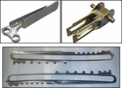
Here are other parts that the plant produces. Cycle time savings for the aluminum part (above) was 50 percent. Cycle time savings for the steel part (below) was 35 percent.
While the modeling software is capable of 3D machining simulations like the one on the facing page, Cessna benefits from the kind of 2D modeling that the results here illustrate.
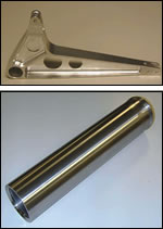
Here are representative titanium parts the plant machines. Starting at top left and moving clockwise, finding more productive parameters for these parts cut cycle time by 59, 31 and 46 percent.
One way to increase machining capacity is to add or improve equipment. At Cessna Aircraft’s Pawnee Road production facility in Wichita, Kansas, investment such as this is a routine occurrence. However, personnel at this facility have also focused their attention on increasing the capacity of existing equipment. Signs of this increase might not be as visible as a new machine hitting the floor, but evidence can still be seen throughout the plant. Specifically, it can be seen on lists that are posted on some of the existing machines.
The lists include part numbers and dates. Each date signifies when the NC program for the corresponding part number was revisited and made more efficient. Tool by tool, part by part, one part number at a time, Cessna engineers are winning cycle-time savings by improving the efficiency of the specific cuts used to machine these existing part numbers.


Sometimes, this improvement involves a change of tooling. This was the case when the plant adopted carbide tools for a titanium part in place of high speed steel. In many other cases, however, the improvement involves simply changing the parameters—the speeds and feed rates—at which the current tools are run.
The cycle-time improvement resulting from such a change is generally significant, says Cessna associate engineer Dhananjay Joshi. On average, revisiting each program to find better speeds and feeds has saved 30 to 35 percent in cycle time. This time savings represents “found” capacity that the plant can use on its existing machine tools.
Was this capacity found because the previous machining parameters were chosen poorly? Not at all. They were chosen according to the best knowledge available to the plant at the time. But today, the engineers use a tool that lets them search for even better parameters easily. “AdvantEdge” software from Third Wave Systems (Minneapolis, Minnesota) lets the Cessna engineers model cuts on computers instead of performing various test cuts on the machines.
Process Remodeling
With so many NC programs to analyze—more than 100 have been revisited so far—Cessna group leader Pravin Kulkarni says it was clear that process modeling would be needed to win significant new capacity out of the plant’s existing parts. Decision-makers at the Pawnee facility were already aware of mathematical modeling’s potential because of the success of finite element analysis in improving the plant’s metal forming operations. Mr. Kulkarni’s group therefore looked at various FEA packages that might be applied to machining. Of these, only the Third Wave software was designed specifically with machining in mind. This made the mathematical modeling dramatically easier to perform; the computational mesh was already defined in the software. As a result, running an elaborate mathematical analysis with this software can involve just inputting relevant data about the material, tool and parameters, then leaving the software to perform its computations and returning later to see the results.
To model so many cuts efficiently without long computation times, Cessna makes effective use of 2D simulations. The system is capable of more detailed 3D simulations as well, but the engineers here have learned to make accurate assumptions about depths of cut in 2D that allow them to generate an ample set of simulations for each cut within a manageable bout of time.
Typically, 10 analyses are run for a given cut. The set includes a matrix of three values of cutting speed times three values of feed rate. An experimenter such as Mr. Joshi chooses mild, intermediate and aggressive values of both sfm and fpt, and matches each of the tested speeds with each of the tested feeds. The tenth analysis is the set of parameters currently being run in production.
The results of this series do not predict cutting performance directly or absolutely, but they do allow relative performance to be inferred from the temperature and force data that the models produce. The Cessna engineers know what forces a particular setup can support, so model predictions of X and Y cutting force reveal whether a cut is appropriate for that setup. Engineers watch the predicted temperatures with a similar limit in mind, because temperature that is too high can lead to a built-up edge that might damage the tool or work. In addition, the engineers use temperature as a proxy for tool life, letting the “tenth” model serve as a baseline. With this model showing how much heat the currently accepted process generates, other sets of parameters can be evaluated to see whether they heat the tool more. If some set of parameters delivers a higher metal removal rate than the current choices, while generating forces that are within the capabilities of the setup and tool temperature that is less than or equal to the current cut, then these results suggest that this new set of parameters is the better choice. New parameters discovered this way are verified through real-life test cutting and then, in all likelihood, adopted into production.
Cessna personnel model milling and turning this way. (Drilling still requires actual cutting.) All of the alloys the plant machines in titanium, aluminum and steel are available as straightforward selections within the software’s material database—another aspect of the software’s ease of use.
Though 30 to 35 percent may be the average cycle-time savings, the modeling has produced extreme savings in a few cases. Mr. Joshi cites the example of a titanium part for which HSS tooling had been assumed to be the best choice. Modeling the process at the manufacturers’ recommended parameters for carbide tools showed that productivity would increase significantly at these speeds and feeds without any corresponding increase in force that might suggest the cut was less stable. Replacing HSS with carbide run at just these parameters would reduce cycle time by 30 percent. However, the Cessna staff then ran the battery of analyses for the new carbide tools to find better parameters for these cuts. After the more efficient speeds and feed rates were found, says Mr. Joshi, the cycle time savings increased to almost 80 percent.


Related Content

5 Tips for Running a Profitable Aerospace Shop
Aerospace machining is a demanding and competitive sector of manufacturing, but this shop demonstrates five ways to find aerospace success.
Read More
Horizontal High-Speed Machining Saves Hundreds of Work Hours
High-speed machining is the latest change at Blair-HSM South, helping this once old-fashioned shop improve productivity and morale while enabling new work.
Read More
10 Things to Know About Creep-Feed Grinding
Because of the high material removal rate creep-feed grinding can deliver in challenging materials, grinding might not be just the last step in the process—it might be the process.
Read More
Modern Bar Feeds Bring New Life to Automatic Swiss Lathes
Cam-actuated Swiss lathes are still the fastest way to process many parts. By adding modern bar feeders, this shop has dramatically improved their utilization with the ability to work unattended, even in a lights-out environment.
Read MoreRead Next

The Cut Scene: The Finer Details of Large-Format Machining
Small details and features can have an outsized impact on large parts, such as Barbco’s collapsible utility drill head.
Read More

3 Mistakes That Cause CNC Programs to Fail
Despite enhancements to manufacturing technology, there are still issues today that can cause programs to fail. These failures can cause lost time, scrapped parts, damaged machines and even injured operators.
Read More