
What Is Single Point OD Grinding?
Two enabling technologies -- superabrasive wheels and high precision servo control -- come together to provide a contour grinding process that resembles an OD turning operation. For many medium volume OD grinding applications, this method may be a means to consolidate several manufacturing steps into a single setup.


This drawing illustrates the compound angle used in Junker's Quickpoint system. Tilting the wheel a half degree allows use of the edge and side for cutting. The wheel's narrow width allows access to most workpiece geometries.
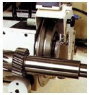
High speed grinding is accomplished by rapid rotation of the workpiece and grinding wheel. Surface speeds of 27,600 sfm allow full use of the aggressive cutting capabilities of the superabrasive wheels used on these machines.
Accuracy for Junker's single point process comes from its CNC and servodrive system. Instead of relying on a form dressed into a wheel, tolerances are held by synchronization of the machine's axes.
The grinding wheel is vitrified CBN or diamond. It is between 4 and 6 mm wide and usually is pressed flat across the face.
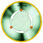
High rotational speeds of the grinding wheels require a repeatable fixture system to assure the wheel runs true. This sketch shows how Junker uses a three-point cam and follower system to achieve 50 millionths (0.000050) of an inch runout repeatability.
Production OD grinding traditionally is composed of process-specific steps. For complex workpieces in a medium-sized batch, these steps are often sequential. The work moves from one process-specific machine to the next. For example, a plunge or step grinding machine will finish bearing races and shoulders, a form grinding machine will clean up tapers and profiles, a thread grinding machine will cut fastening threads, and so on.
Individually, each process step is performed very quickly. An analysis of the total throughput time, however, reveals that significant savings could be made if work handling between operations could be reduced or eliminated. Additionally, keeping a workpiece on a single machine provides better workpiece accuracy because dimensional relationships between workpiece features can be maintained.


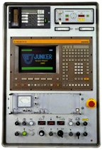
Single point grinding is a process that enables one machine to perform several grinding operations without removing the workpiece from the machine. Junker Machinery (Springfield, Massachusetts) uses this process on a line of machines it calls Quickpoint.
They claim that total process savings using this approach can be six times that of conventional OD grinding. We talked to Markus Lipphardt, sales manager, and Edger Obert, vice president, about how the single-point grinding process works and how its application can benefit grinding shops.
It's The Point
The basic idea for single point grinding comes from the modern CNC turning center, which offers a big advantage for shops doing turning work because a single cutting tool can be used to perform various operations. For example, one single point tool can profile, face, plunge and even cut threads.
In operation, an OD grinding machine is similar to a turning center. Two axes of movement are generally involved in both metalcutting processes. On turning centers a form tool can be used to cut profiles, or a single point cutter can be programmed to follow a desired profile through synchronization of X- and Z-axis motions.
Many conventional OD grinders use a wheel with a desired geometric profile dressed into the wheel. Once a dressing or truing unit profiles the wheel, that profile is then imparted to the workpiece by movement of one or both of the machine's slides.
Single point grinding uses a process that imitates single point turning—a single grinding wheel is used to perform a variety of operations. Profiling, plunging and threading are accomplished by precise control of the X and Z axes by CNC through servomotor and ballscrew actuation. That control is key to single point grinding because the workpiece shape is ground by the synchronized movement of the machine axes and not by a profile that's dressed into the grinding wheel.
On conventional OD grinders, the wheel/workpiece interface forms what is basically a line of contact between the face of the wheel and the work. For example, if one lays two pencils side-by-side with one representing the workpiece and the second the grinding wheel, contact between them forms a line. A wider wheel contacts more of the workpiece.
In single point grinding, a narrow (4 to 6 mm) grinding wheel is used. The wheel is dressed flat across its face. Using the two parallel pencils again as an example, swivel the pencil representing the grinding wheel half a degree. Now the contact area between the two is a single point. Basically, that model represents the wheel/workpiece contact in single point grinding. The grinding wheel's angle of attack presents an edge of the wheel that makes the contact between the wheel and workpiece tangential.
High Speed Cutting
The relatively small contact area between the single point grinding wheel and the workpiece reduces the cutting forces generated by the metal removal process. Reduced cutting forces generate less heat so the single point grinder can be run at higher cutting speeds without causing surface damage to the workpiece.
Cutting speeds of 27,600 sfm are possible with superabrasive (CBN or diamond) grinding wheels. These speeds fully utilize the aggressive cutting capability of the wheels. "Most applications have the single point grind complete in one pass," says Mr. Obert.
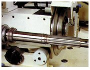
Because grinding wheel rotation is limited by centrifugal force, these high speeds are not achieved by the wheel alone. Junker's machines are used primarily to grind automotive drive train components. In transmissions and drive trains, these workpieces must rotate, sometimes at high speed. Therefore the workpieces tend to be symmetrical.
To achieve the high metal removal rates mentioned above, a combination of wheel surface speed and workpiece surface speed is necessary because the wheel's speed is limited by safety concerns. In order to augment the wheel speed, workpieces can be rotated up to 12,000 rpm. The high surface speed achieved with single point grinding is a sum of workpiece rotation plus the rotation of the grinding wheel.
Rotating a workpiece at these speeds requires a balanced setup. The low cutting forces generated by single point grinding simplify the workpiece drive mechanism. "In most applications we've seen on these machines, drive dogs or other workpiece drivers are not necessary," says Mr. Obert. "The frictional pressure of the center is sufficient to maintain part rotation. This definitely helps contribute to a balanced setup."
The Wheel
"Most applications use a vitrified bond superabrasive wheel," says Mr. Obert. "Originally metal bond wheels were recommended for this process but dressing these wheels was very time consuming. Advances in vitrified superabrasive bonds now make them practical for single point grinding."
However, these wheels tend to be rather coarse. Advantages include aggressive cutting action and reduced frequency of wheel dressing. On the down side, surface finishes of 7 rms are about as good as can be achieved.
Feedlines also impact how fine a finish can be ground with the single point process. These lines border on microscopic but are imparted onto the workpiece nonetheless. "If lower finish numbers are necessary, a subsequent superfinishing operation may be needed," says Mr. Obert.
Single point grinding is a unidirectional process. Grinding of OD workpiece features progresses from right to left or vice versa. "Wheel wear is the reason for this process requirement," says Mr. Lipphardt. "Wear tends to migrate across the face of the grinding wheel. Therefore to achieve consistent contact, grinding needs to be unidirectional."
Moreover, because the wheel cuts on one edge, its opposite edge—which is dressed square—can be used to cut shoulders. "It can cut only one side of a shoulder, however," says Mr. Lipphardt. "For right and left shoulders, the wheelhead must be indexed 180 degrees to allow the same side of the wheel to cut both shoulders. The index takes seconds. Some machine models have a second wheel for jobs with numerous shoulders."
Junker says that a G-ratio of 60,000 is achievable with single point grinding using superabrasive wheels. G-ratio is the relation between metal removal and wheel wear. For example, a G-factor of 60,000 in wheel wear means 60,000 cubic inches of metal will be removed.
A Positive Tilt
On various models of the Junker Quickpoint, the grinding wheelhead can be programmed to swivel zero to 30 degrees perpendicular to the workpiece. Junker's single point process compounds the angularity of the wheel by tilting it ±0.5 degree in the vertical plane.
"This tilting of the wheel is critical to getting free cutting action from the single point process," says Mr. Lipphardt. "In effect, the tilt brings more of the side of the wheel into the cut, which in turn brings more cutting grit into the grind. This slightly skewed contact also reduces the severity of spiral cut lines as found on single point turned parts. Most of the cutting is done with the side of the wheel."
A hydraulic cylinder actuates the grinding wheel tilt. It moves ±0.5 degree by an M-code command from the CNC. Control of the travel is by a hard stop that the tilt mechanism rests against.
Cutting forces are reduced significantly because of the combination of swivel angle and wheel tilt. The area of contact is much less than a conventional OD grinding wheel.
Reduced cutting forces lessens the heat buildup on the workpiece, making thermal impact less of a consideration. Coolant application is simplified with the single point concept because the fluid needs only to reach a relatively small area of intersection between the wheel and work.
Accuracy
Grinding accuracy of the single point process is a function of the machine tool's accuracy. It relies only on the positioning and repeatability capabilities of the grinder.
"Single point grinding eliminates one source of potential grinding inaccuracy," says Mr. Lipphardt. "The wheel dresser or truing unit has a tolerance band. A grinding machine has a positioning and repeatability tolerance. If one can eliminate profile dressing and replace it with servo control, then only the machine's tolerance band is involved in generating workpiece accuracy."
Single point grinding allows the shop to process cylindrical, tapered contours, plunge cuts, shoulders and slots in a single chucking. Instead of dressing a specific taper or contour into the grinding, workpiece features are ground by simultaneous control of the Z-axis infeed and X-axis table positioning.
Both axes use closed-loop digital servo feedback through the CNC and are actuated by precision, anti-backlash ballscrews. Positioning scales are used on both axes.
A CNC program, which can be input at the machine or downloaded from a remote location using a variety of network protocols, directs the wheel and table to follow simple or complex geometry with an accuracy within two microns. "Where this process really comes to the fore," says Mr. Obert, "is medium runs and families of parts where traditional grinding methods would require long wheel dressing cycles or transfer between several machines. Single point grinding eliminates profile dressing entirely and cuts most workpiece geometry in a single chucking. Only periodic cleanup of the wheel is needed."
Quick Change Wheel
Critical to optimum operation of superabrasive grinding wheels is good balance and virtually no runout. For balance, the grinding wheel spindle uses an electronic balancing system that is built into the spindle. Balance is automatic.
To keep runout to a minimum and ensure repeatability between wheel changes, Junker's machine uses a unique fixture system. "This system keeps wheel runout to 50 millionths [0.000050] of an inch. And, the specification is repeatable between wheel changes," says Mr. Obert
A three-point centering system is built into the wheel and flange. Three cam followers are installed on the periphery of the wheel core. A three-lobed cam is machined into the flange plate. When the wheel and flange are mated, a partial turn of the flange engages the cam followers that self-center the wheel on the flange. Once the wheel is properly located, it is secured by bolts.
A scaled version of this centering system is used for both centers. In addition to quick changeover considerations for setup and tear down of jobs, the self-center system provides accurate positioning of the workpiece between.
What's It Good For?
Implementing single point grinding could be the solution for many production grinding shops. It's especially efficient because the process requires fewer machines to produce the same lot quantities as a line of single purpose machines. Direct and indirect cost savings can be realized, from the need for fewer operators to lower maintenance and consumables.
While single point grinding is well applied to complex and varied workpieces, its high surface speeds—which are possible by combining the wheel rotation and workpiece rotation—permit high traverse rates, which make the process competitive with straight plunge and other conventional grinding operations for producing relatively simple geometries.
"In applications where there is complexity, single point grinding will do a better job," says Mr. Obert. "The narrow grinding wheel allows access to features that a conventional wheel cannot get to without significant dressing down. Varying widths of flat and tapered surfaces, crowned surfaces, slots and undercuts can all be accessed by a single point process."
The use of superabrasives also enhances the flexibility of the single point process for use in a variety of materials. In one application, an electric motor rotor composed of three distinct materials was ground in one setup.
"This rotor had a soft steel shaft with an aluminum armature pressed on the shaft, says Mr. Obert. "Tungsten carbide was used on the shaft as contacts for the bearings. All three materials were ground using two wheels, a diamond for the tungsten carbide and CBN for the soft steel shaft and aluminum. Concentricity was maintained because the workpiece was ground complete in one chucking."
The Need
The grinding process has been under fire for some time now. Many shops are looking at alternative methods to reduce or eliminate grinding from their process. Hard turning is one example.
Single point grinding may be a way to use the accuracy and surface finish benefits of the grinding process in a way that has a lower impact on the material flow in the shop. In virtually all metalworking operations including milling and turning, many businesses are looking to perform more operations in a single workpiece handling.
For medium volume production grinding of complex workpieces, a single point grinding process may be a way to accomplish this for shops that grind for a living.


Related Content

Threading On A Lathe
The right choices in tooling and technique can optimize the thread turning process.
Read More
10 Things to Know About Creep-Feed Grinding
Because of the high material removal rate creep-feed grinding can deliver in challenging materials, grinding might not be just the last step in the process—it might be the process.
Read More
A New Milling 101: Milling Forces and Formulas
The forces involved in the milling process can be quantified, thus allowing mathematical tools to predict and control these forces. Formulas for calculating these forces accurately make it possible to optimize the quality of milling operations.
Read More
How to Reduce Cycle Times by 70% and More on Your Existing CNCs and Dramatically Improve Tool Life Too
By employing advanced high efficiency milling techniques for the entire machining routine, SolidCAM’s iMachining technology can drastically reduce cycle times while vastly improving tool life compared to traditional milling.
Read MoreRead Next

The Cut Scene: The Finer Details of Large-Format Machining
Small details and features can have an outsized impact on large parts, such as Barbco’s collapsible utility drill head.
Read More

3 Mistakes That Cause CNC Programs to Fail
Despite enhancements to manufacturing technology, there are still issues today that can cause programs to fail. These failures can cause lost time, scrapped parts, damaged machines and even injured operators.
Read More