
A Different Differential
Differential gaging offers several advantages over single-head measurements.

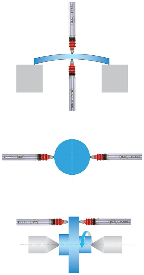
Fig. 1 - When the two gage heads are in line and in an opposed position, the sensed dimension will be the change in the separation of the two tips--in this case, the size of the part.
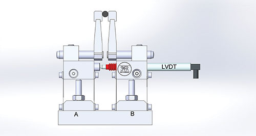
Fig. 2 - In this simulation of a mechanical differential check using friction-free panto-transfer units, if we held panto A fixed and moved panto B, the LVDT (transducer) would move and the amount would be shown on its readout.


When we talk about differential gaging, we are usually referring to the process of using two sensing devices and combining the results into one measurement. The measured dimension is the change in the position of the two sensing components.
We’ve talked before about why differential gaging has some advantages over normal, comparative measurements using a single sensing head against a fixed reference surface. These include the measurement of size without regard to position (see Figure 1). When the two gage heads are in line and in an opposed position, the sensed dimension will be the change in the separation of the two gage tips—in this case, the size of the part.
When we measure in this manner, the staging of the part does not become part of the measurement loop. The platen in a differential system just places the part between transducers. With a single-head system, the platen is part of the measurement loop, and therefore flatness and configuration of the platen is critical.
There are a number of different measuring systems available that can provide differential gaging, including air and electronic gaging. Air gaging is probably the most common, since every two-jet air plug and air ring utilizes the differential gaging principle. Most air gages measure back pressure that builds up in the system when the tooling is placed in close proximity to a workpiece; this results in higher air pressure, which the gage comparator converts into a dimensional value. Thus, as the plug fits into the part, it is the combination of both jets that represents the diameter of the part, without regard to where in the part the plug happens to be.
The same is true with electronic probes. In this case though, the probes are combined electronically to provide the differential measurement. Differential gaging with both air and electronic probes is used in a wide variety of applications that include measurement of form on angles and tapers and shafts without regard to the part dimensions; concentricity of two shaft diameters; comparing a workpiece to a master; match gaging; and checking parallelism of a workpiece and its support surface.
However, there is another form of differential measurement that is probably not used as often as it could be. This mechanical method provides the same results as air or electronic gage-based differential measurement, but it requires only a single sensing head. It accomplishes this by providing a means for the body of the indicator, which becomes the second sensing head, to move along with independent movement of the contact itself. Since the system uses only one sensing head, it can provide very high performance in a much smaller space.
Figure 2 shows an example of a simulation of a mechanical differential check. In this case we are simulating the measurement of a ball, but it very well could be any other type of length measurement. The method uses friction-free panto-transfer units, but they could be any high-precision ball slide. By looking at the figure we can see that if we held panto A fixed and moved panto B, the LVDT (transducer) would move and the amount would be shown on its readout. On the other hand if panto B was held fixed and A was allowed to move, the plunger of the transducer would be the sensing portion and the motion would also be shown on the indicator. Once both are allowed to move, the combination of both panto transfer units make up the differential measurement, without regard to where the part is located within the range of the measurement heads.
Making use of this simple but effective method can produce equal and sometimes superior results. This technique can be very handy in situations where there are space limitations and two transducers don’t fit into the gaging station.


Read Next

3 Mistakes That Cause CNC Programs to Fail
Despite enhancements to manufacturing technology, there are still issues today that can cause programs to fail. These failures can cause lost time, scrapped parts, damaged machines and even injured operators.
Read More
The Cut Scene: The Finer Details of Large-Format Machining
Small details and features can have an outsized impact on large parts, such as Barbco’s collapsible utility drill head.
Read More
