
Approximating Geometry Measurement
We have all run across cases in which matching parts that measure “okay” don’t seem to quite fit together. This often happens with ID and OD parts that tend to have very tight clearances, typically within a few 0.0001 inch.


Figures 1 and 2
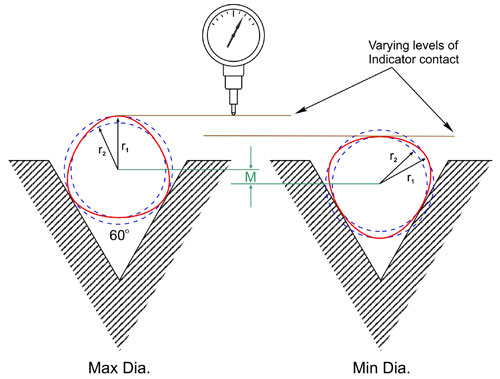
Figure 3

George Schuetz


In these cases, you need to know more about the part’s geometry. Just as we cannot make parts perfectly to size, neither can we make them perfectly round. And as we all move toward tighter-tolerance machining, irregularities in shape will have a greater effect on our ability to make parts. By understanding the process that makes the part—and which often determines part geometry—we can be sure to apply the best gaging for the application.
In lab analysis of some parts, it is not unusual to see a consistent three-lobed, out-of-round condition which makes the parts’ effective diameters too large. The condition is very common when using centerless grinding, but it is often not noticed because: 1) the part specs don’t call for any geometric analysis; and 2) the shop only uses a two-point dimensional gage, which is incapable of detecting the problem.
Understanding the geometry involved is the key. Out-of-roundness is either symmetrical, involving regular or geometrically arranged lobes or points on the part’s circumference, or asymmetrical, where the lobing is not regular. Most machining processes create symmetrical lobing, producing either an even or an odd number of lobes. Even-number lobing is sometimes seen in precision boring operations, caused by a worn or out-of-balance spindle. Odd-number lobing can be caused by a three-jaw chuck (producing a three-lobed workpiece) or a centerless grinder (which can also create a five-lobed condition). Asymmetrical lobing cannot be measured by the means described here, but it is evidenced by irregular travel of an indicator and usually indicates a problem in the tool.
In cases where an even number of lobes are arranged symmetrically on the part, each lobe is opposed by one diametrically opposite (see Figure 1). Thus, the piece will have major and minor diameters. Knowing this, we can gage the part by taking multiple measurements using two-point or diametrical-measurement methods.
The difference between the maximum and minimum of these measurements will generally be twice the out-of-round value because of the diametrical versus radial method of assessment. For example, if our specs call for a part that is “round within 0.0001 inch variation in radius,” we can measure using a simple comparator and reject any part where the Total Indicator Reading (TIR) is larger than 0.0002 inch.
Figure 2 illustrates the relationship between out-of-roundness and effective diameter on a three-lobed part. In this case, any two-point measurement will yield a consistent diameter because each lobe is geometrically opposed by a flat area. This measured dimension would fall somewhere between the inner and outer dotted circles. However, the effective diameter, or the amount of space this part would actually require to clear, would be the outer dotted circle, which encompasses all the lobes.
For an OD, the geometry gage is going to be the best method for checking this form error, but a simple V-block fixture with the blocks at 60 degrees can also measure the effective diameter (Figure 3). If the part needs to be kept in the gage to be measured, an air ring with three jets is the solution because having the jets at 120 degrees matches up perfectly with the highs and lows of the lobes on the part. Now the part can be rotated and the gage display will show the diameter variation.
In a similar example, a part is produced on a CNC lathe using a three-jaw chuck, and we have previously determined (possibly through the use of a circular geometry gage) that the process generates a three-lobed condition. Therefore, we use a gage having a V-block fixture set up with a 60-degree included angle. To determine allowable variation in radial out-of-roundness, multiply 0.0001 inch by 3. Any TIR larger than 0.0003 inch is out of tolerance.
Similarly, air gaging can be used to check diameter variation on IDs. Typical bore gages are based on a two-point principle, which is exactly what we don’t need with a three lobe condition. Air tooling can employ three jets—located at 120-degree intervals—which act like an inside-out V-block. As the air plug is inserted into the hole and rotated, the air gage will go through a high point and low point every 120 degrees, thus assessing the odd lobing condition.
Bear in mind that while these techniques provide a practical means to determine out-of-roundness on the shop floor for both IDs and ODs, the measurements are only approximate.


Read Next

3 Mistakes That Cause CNC Programs to Fail
Despite enhancements to manufacturing technology, there are still issues today that can cause programs to fail. These failures can cause lost time, scrapped parts, damaged machines and even injured operators.
Read More

The Cut Scene: The Finer Details of Large-Format Machining
Small details and features can have an outsized impact on large parts, such as Barbco’s collapsible utility drill head.
Read More