Charting Roughness For Grit-Blasted Surfaces
When an engineer includes a surface finish spec on a print, the intent is usually not just to make the part look good. Surface finish affects how a part will fit, wear, reflect light, transmit heat, distribute lubrication and accept coatings. The finish should be determined by the part’s function: A surface should fulfill engineering requirements without producing a higher-quality finish than necessary.
Surface finish, also known as profile, includes two components: waviness and roughness. Waviness, or longer-wavelength variation, is caused by macro-type influences such as worn spindle bearings or vibration from other equipment on the shop floor. Roughness is the short-wavelength pattern of tool marks from grinding, milling and other machining processes, and it is affected by the condition and quality of the tooling. Both components can be influenced by the operator’s choice of feed rate and depth of cut.
Most surface finish checks are performed on machined surfaces, where the finish is created by a cutting tool that is run across a surface. However, there are other ways of creating a surface finish, and it is important to ensure that those resultant surfaces also meet design requirements.
We recently consulted on a large pump housing application where, rather than machining the surfaces, grit blasting was used to produce a surface with specified peaks and valleys so that it could be thermal-spray coated. The correct abrasive blast cleaning of the surface resulted in a number of peaks and valleys with a depth that exposed a maximum area of steel. The purpose of exposing the maximum amount of steel was to produce greater area for the coating to bond to, thus improving coating life.
Normally, Ra is used to measure the roughness of a surface, but for these grit-blasted surfaces, the single average roughness number was not enough. The manufacturer needed to generate a roughness profile of the surface with a graph so it could evaluate various grit-blast methods. Using a chart of the surface also allowed the company to ensure that peak-to-valley heights were uniform and consistent throughout the evaluation area.
A second requirement for these grit-blasted surfaces was to measure the actual roughness of the surface being produced and ensure that roughness specifications were being followed. Depending on the grit material, the resultant surface could require measuring Ra ranges of 0.010 inch or more. These are much higher than a typical machined surface, but were nonetheless just as critical to the performance of the surface in holding the coating.
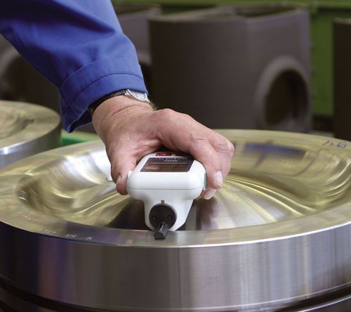
The final requirement for this particular application was that the surfaces be measured in place. The grit-blasted parts were large and could not be brought to a bench-mounted surface finish gage. Therefore, surface finish parameters had to be measured on the shop floor next to the blasting machines.
The gage chosen for this application was one of a new generation of portable surface finish gages, which offers more capability that older handhelds. Weighing 14 ounces, the selected gage can measure more than 24 surface finish parameters with a high-resolution, inductive probe. The gage also features expanded memory, USB connectivity, optional PC software, a large measuring range and relatively low cost. For this application, the key was the ability to store and output trace data to generate the needed Ra charts. The gage and traces could then be brought back to review the surface and ensure that it was uniform for the coating application.
The data that can be obtained about a surface is invaluable to the performance, improvement and life of the product that bears it. By understanding the profile plots of Ra, Rz and Rmax data, decisions can be made that help produce the desired surface finish requirements in the fastest possible time and reduce over-finishing the parts.
Many surfaces machined or manufactured today have a specific purpose. The only way to understand, control and qualify the surface for its purpose is to measure and understand it.
Read Next
The Cut Scene: The Finer Details of Large-Format Machining
Small details and features can have an outsized impact on large parts, such as Barbco’s collapsible utility drill head.
Read More3 Mistakes That Cause CNC Programs to Fail
Despite enhancements to manufacturing technology, there are still issues today that can cause programs to fail. These failures can cause lost time, scrapped parts, damaged machines and even injured operators.
Read More


.png;maxWidth=300;quality=90)


