Published
Checking the Performance of Surface Finish Gages
The measurement of surface finish has come a long way in the past 60 years. We have advanced from fingernail scratch pads to microprocessor- and PC-based systems with inductive probes. We even have the choice of optical sensors to evaluate part surfaces.
Although fingernail scratch pads may provide a usable guide to finish, they cannot meet the modern requirements of quality documentation and traceability of surface finish instruments. That is why there is increasing importance of calibration and certification for surface finish gages.
One of the great things about measuring surface finish is that the measuring process and parameters are clearly defined in industry standards such as ASME B46.1-2002, along with international standards ISO, DIN and JIS. The standards help define the specification of the instruments, how they are used, the results they provide and how they can be tested for performance. Let’s look at the way the standards approach the calibration process.
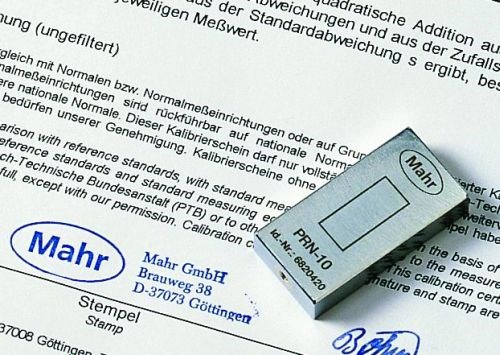
As we know, surface finish is made of a series of peaks and valleys machined or otherwise manufactured on the surface of the part. Surface calibration standards, specimens or patches contain peaks and valleys in various shapes and amplitudes that are precisely machined, then measured and certified as traceable to international standards. The calibration process verifies that the surface finish instrument is producing accurate results.
Let’s look at roughness measurements taken on skidded measuring systems as an example. The most common roughness standard is the triangular style with rounded peaks and valleys. From the ASME B46.1-2002 standard, these specimens are typically referred to as “C3 Style” grooves, and they are available in various grades of roughness. Examples include Ra values of 0.5, 0.9, 2.5, 3.0 or 3.2 microns.
It is important to make sure the system you are using has the same diamond tip radius as the one used to calibrate the specimen. Smaller or larger radius tips will fall into the peaks and valleys differently, so the results from these probes will vary. You can always ask the calibration lab that certifies your specimen to use the same diamond radius you are using.
Conventional wisdom for the calibration process says to use a specimen that is close to the values required for your process. For example, if you are measuring very fine surfaces, you should use a fine calibration patch. However, this may not be the best idea. As with any gaging amplifier, which is what a surface finish instrument really is, it is best to calibrate using as much range as possible. The benefit of this is that you are exercising the probe and amplifier over their full range to ensure proper operation anywhere within the calibration range. Thus, you may not have to precisely put the probe to the true mechanical zero for good performance. However, with any calibration process, it is best to check the instrument manufacturer’s calibration procedure.
After the full range calibration, it is wise to verify the performance with a fine calibration patch. This is important for two reasons: First, it will verify that your instrument is producing the correct results after the calibration. Second, if the result is not right, it probably is not the calibration but rather the wear of the diamond radius tip. As the diamond wears or becomes chipped, it will either span or go further into the valleys and give improper results.
The checking process is fairly simple. Just make a measurement of the surface reference specimen with the instrument using the Ra parameter and see what you get. Each reference specimen is available with a certificate of what the measured Ra value is. After the test, compare the results. It should be within the percentage of error as specified by your instrument manufacturer. If not, perform the calibration procedure again, then re-measure the reference specimen. If the results still are not accurate, there may be an issue with the unit or the probe. This two-step process gives you a double check: one of the system and one of the probe.
Read Next
Large Part Machining
The Cut Scene: The Finer Details of Large-Format Machining
Small details and features can have an outsized impact on large parts, such as Barbco’s collapsible utility drill head.
Read More3 Mistakes That Cause CNC Programs to Fail
Despite enhancements to manufacturing technology, there are still issues today that can cause programs to fail. These failures can cause lost time, scrapped parts, damaged machines and even injured operators.
Read More


.png;maxWidth=300;quality=90)


